9. Operation using a marking device
Reference Manual |Edition 4.0 (10-2013) |EcoCut 3300
53|108
OPERATION USING A MARKING DEVICE
9.1
INFORMATION FOR WIRE MARKING
▄
Only program the marking when the wires are being cut accordingly or temporarily enter
0
(sample
wire) in the „Marking (marker)“ menu. This way any wire loss can be held on a minimum.
▄
The
EcoCut 3300
automatically calculates the wire loss (waste piece) that takes place during the start
of the processing. The distance between the marking device and the
EcoCut 3300
has no influence on
the resulting production quantity.
▄
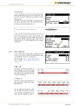
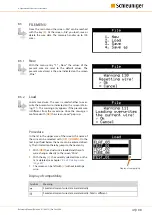
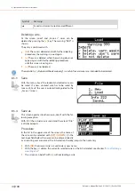
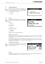
To obtain only one print enter the position „Right" in the screen "Wire marking".
▄
To obtain a print in the middle of the wire, enter half the wire length in the „Right" position.
▄
If the entire typeface has shifted, the distance between marking device and the
EcoCut 3300
has to be
measured and reprogrammed.
9.2
INSTALLING THE WIRE MARKER UNIT
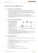
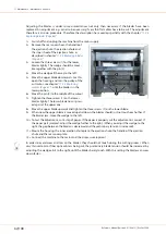
1» Install a HotStamp left next to the
EcoCut 3300
(see also the operat-
ing manual HotStamp). The pro-
cessing axis of both devices must
be aligned in the X- and Y-axis.
2» Plug the connecting cable into
the interface
„HS/PF“
.
If a
Schleuniger
HotStamp device
is used the connection cable is
enclosed.
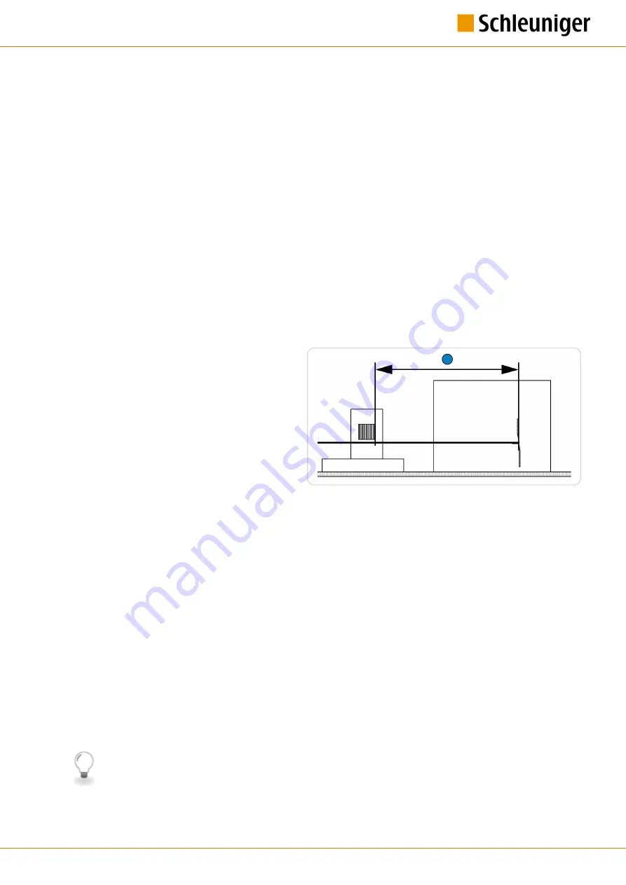
3» The distance (1) from the cutting
axis (blades) of the
EcoCut 3300
to
the right side of the printing wheel edge should not exceed 1 m.
4» Fasten the device securely. The distance should not be changed during operation (applies specially
to the
EcoCut 3300
, if applicable use the original
Schleuniger
machine rack).
5» In order to correctly position the marking, the distance (1) between the
EcoCut 3300
and the marker
device must be entered into the
EcoCut 3300
.
9.2.1
Determining the distance
Determine the distance (1) as follows:
1» Measure the distance (mm) with a measuring tape from the right printing wheel edge to the cutting
axis.
2» Switch on both devices
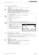
3» Enter the distance in the menu "Configuration - HotStamp", see chapter
"8.6.1.2.1 Distance (Page 45)"
4» Choose the desired pulse duration (in ms).
➥
During the pulse duration, the output of the „HS/PF“ interface is activated.
5» Leave the screen.
6» Program a wire with a marking.
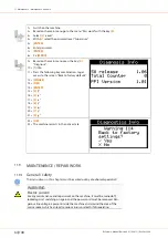
Determine the distance conveniently:
1» Load a wire on both devices (make sure that the wire was cut).
2» Carry out a test marking.
3» Press
[FEED]
until the marking of the wire is visible on the
EcoCut 3300
exit.
1
Cutter
Summary of Contents for EcoCut 3300
Page 8: ...Table of contents 8 108 Reference Manual Edition 4 0 10 2013 EcoCut 3300...
Page 22: ...4 Product specifications 22 108 Reference Manual Edition 4 0 10 2013 EcoCut 3300...
Page 74: ...12 Spare parts exploded view drawings 74 108 Reference Manual Edition 4 0 10 2013 EcoCut 3300...
Page 76: ...13 Decommissioning disposal 76 108 Reference Manual Edition 4 0 10 2013 EcoCut 3300...
Page 102: ...14 Appendix 102 108 Reference Manual Edition 4 0 10 2013 EcoCut 3300...
Page 103: ...Personal notes Reference Manual Edition 4 0 10 2013 EcoCut 3300 103 108...
Page 104: ...Personal notes 104 108 Reference Manual Edition 4 0 10 2013 EcoCut 3300...
Page 107: ......
Page 108: ......


