background image

6 Installation 


Operating Instructions | Version 1.0 (05-2018) | Uni-M Ferrule 

20 | 32


6.1.4


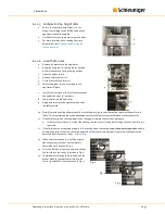
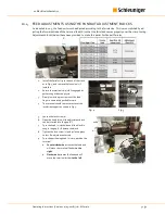
Remove the applicator  

1.


Raise the press ram to the top. 

2.


Remove air pressure. 

3.


Open the shield.  

4.


Install the red tooling protection ring (1). 

5.


Remove the hose fitting from the quick connect 
on the applicator. 

6.


Release the base plate lever.  

7.


Ensure a firm grip on the applicator and remove 
it to the left.  


6.2


ADJUSTMENTS 

INFO


Always confirm quality!


After making any adjustments, always confirm crimp quality according to the given specifications. 

6.2.1


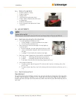
Reading and adjusting the crimp height dial 

1.


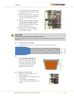
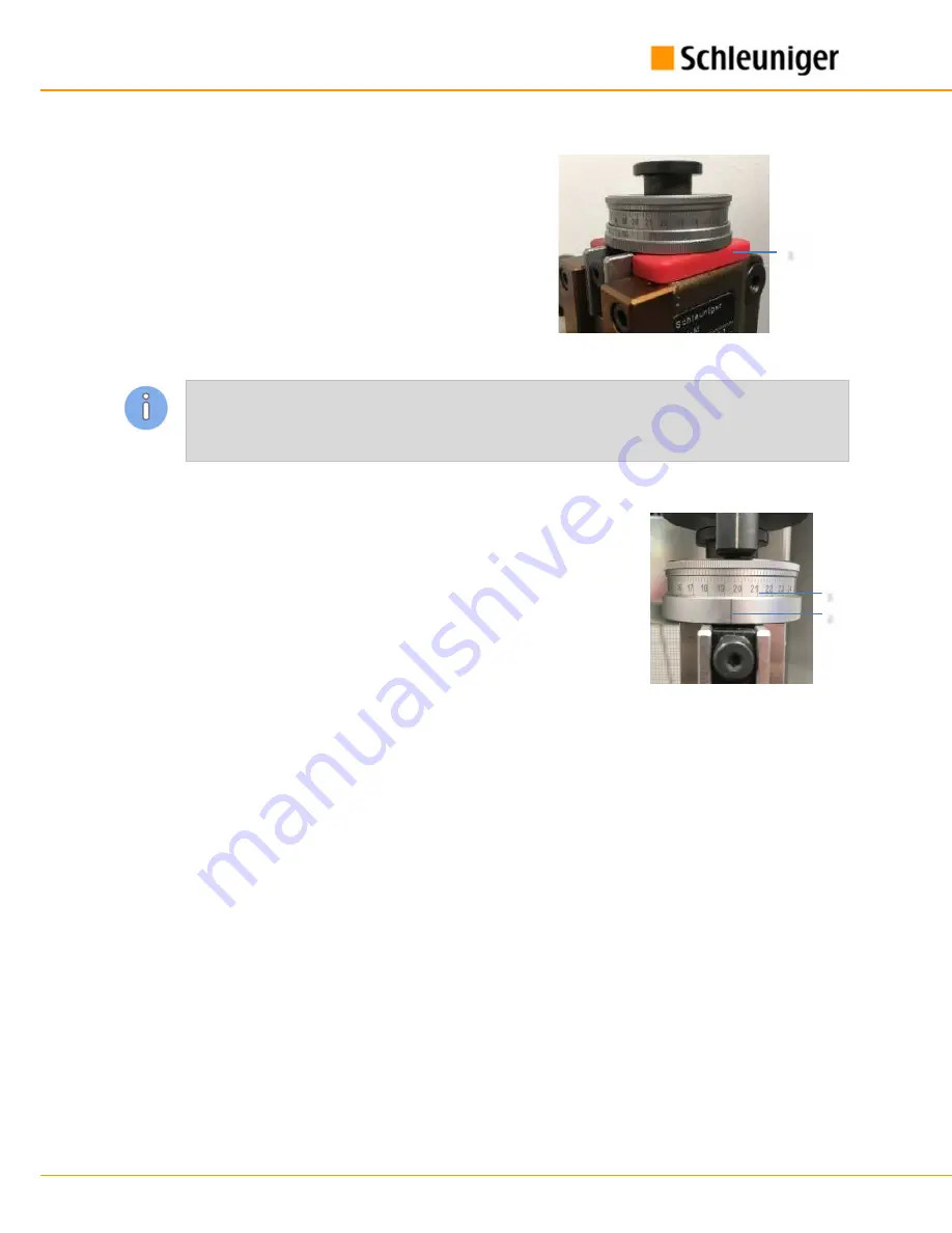
The crimp height adjustment dials consist of: 

a.


A dial (1) labelled 0 – 27 to adjust the conductor crimp height. 

b.


A lower ring with a reference mark (2).  

2.


Each increment (or click) of the dial changes the crimp height by a 
0.01mm (0.0004”).  

a.


Reduce crimp height by turning the top dial clockwise (to the left). 

b.


Increase crimp height by turning the top dial counterclockwise (to 
the right). 

c.


A setting of “0” (zero) results in the maximum crimp height. 


4.


Each major increment represents an index value of the number divided by 10 
a.


Examples:  

Dial setting on 8 refers to an index value of 0.8. 

b.


Example:  

Dial setting on 19 refers to an index value of 1.9.  

a.


Photo shown of the dial refers to an index setting of approximately 1.95. 

5.


Setting the dial index values. 

a.


To achieve an index value of 0.85, start at “8” on the crimp dial (1) and turn it clockwise 5 clicks (0.80 + 
5*0.01 = 0.85) 

b.


To achieve an index value of 1.23, from “12” on the crimp dial (1), turn it clockwise 3 clicks (1.20 + 3*0.01 = 
1.23) 

6.2.2


Back stroke adjustment 

Proper adjustment 

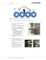
During the backstroke, the feed finger must pass over at least one full ferrule. Depending on the range of fer-
rule sizes, it may be necessary to pass over 1.5 or more ferrules so that the entire range may be processed in 
the same applicator. As long as the forward stroke only advances one ferrule, then the backstroke position is 
not critical. 

Summary of Contents for Uni-M

Page 1: ...Uni M Ferrule Applicator Pneumatic feed Operating Instructions Version 1 0 05 2018...

Page 2: ...Operating Instructions Version 1 0 05 2018 Uni M Ferrule 2 32...

Page 3: ...Limitation of liability 7 1 6 Warranty statements and policies 7 1 7 Copyright protection 7 1 8 Spare parts 7 2 Safety 8 2 1 Warning notices 8 2 2 General safety notes 8 2 3 Sources of danger risks 8...

Page 4: ...15 6 Installation 16 6 1 Setup 16 6 1 1 Confirm shut height 16 6 1 2 Install applicator in press 16 6 1 2 1 Mounting 16 6 1 2 2Air connection 17 6 1 2 3 Confirm clearance 17 6 1 2 4Activate split cyc...

Page 5: ...nance schedule 24 7 3 1 Check tooling 24 7 3 2 Cleaning 24 7 3 3 Lubrication of components 25 7 4 Repair work 25 7 4 1 Tooling replacement 25 8 Spare parts 28 9 Decommissioning 29 9 1 Disassembly 29 9...

Page 6: ...rained and have read and understood the Operator s Hand book This is also imperative even when the respective person has operated such a product or similar previ ously and where they have been trained...

Page 7: ...was put together taking into consideration the current standards and guidelines according to the state of the technology and our many years of experience The manufacturer disclaims any liability for d...

Page 8: ...ss prior to the start of operation Never operate the product in an explosive or flammable environment Before performing any maintenance or repair work remove the air supply from the applicator when ap...

Page 9: ...ON AND RETROFITTING To avoid any dangerous situations and for an optimal performance it is not allowed to make any modifica tions to or retrofitting of the product without explicit written permission...

Page 10: ...While working on the product always wear protective equipment according to the local regulations to mini mize the risk of injury 2 8 1 Eye protection To protect the eyes from small particles produced...

Page 11: ...ry or only with exceptions Declare loss of shipment Immediately report damages on the product NOTICE Packaging notice If provided observe the packaging notice on the machine Please dispose of waste ap...

Page 12: ...ll the red rubber crash protection ring 1 whenever the applicator is not installed in a press Handle the packaging with care Observe the packaging signs Wherever applicable remove the packaging not be...

Page 13: ...tion in the press Do not operate an applicator in a press without the proper upper and lower adapters Operating the applicator in a press without proper fixation could result in damage to the press or...

Page 14: ...rter kit holder 4 Feeding finger 5 Brake lever 6 Backstroke adjustment screw 7 Wire crimp height adjustment 8 Ferrule cut off tool 9 Upper ram knob 10 Terminal feed adjustment knob 11 Terminal feed co...

Page 15: ...al feeds into position over the crimp anvil after the crimp cycle has started post crimp This method is more common for automatic termination applications This method allows more time for the crimped...

Page 16: ...t of the press must be set to 135 78 mm 0 02 mm 5 346 0 0008 Confirm the setting is accurate with either and electronic press analyzer or a mechanical shut height gauge For shut height adjustment plea...

Page 17: ...ge whenever any applicator is loaded into a press the press should be cycled slowly or manually to ensure the tooling will not crash 6 1 2 4 Activate split cycle mode The Uni M ferrule applicator requ...

Page 18: ...ly lower the tooling either manually or with the press jog so that the tooling captures the next ferrule Note This may require a few cycles depending on where the ferrule strip is with relation to the...

Page 19: ...crimping CAUTION Confirm proper ferrule position before initiating a full cycle To prevent tooling damage before initiating a full crimp cycle verify that the ferrules are in the proper position in th...

Page 20: ...he left b Increase crimp height by turning the top dial counterclockwise to the right c A setting of 0 zero results in the maximum crimp height 4 Each major increment represents an index value of the...

Page 21: ...inger to the left which increase the backstroke b Clockwise moves the finger to the left which decreases the backstroke 5 Tighten the lock nut 2 on the screw 6 Slowly cycle the press and confirm posit...

Page 22: ...over it as seen in Fig 1 9 The cut off blade 4 comes down and pushes the ferrule into the cavity 5 as seen in Fig 2 10 The blade cuts through the insulation and the pusher blade 6 pushes the ferrule i...

Page 23: ...trained personnel CAUTION Use of unverified parts Unverified or defective spare parts can lead to personnel injury or property damage To avoid any damage exclusive use of original Schleuniger spare pa...

Page 24: ...email support at TSInbox schleuniger com 7 3 MAINTENANCE SCHEDULE Maintenance Task Section Duration Interval Personnel qualification Check tooling 7 3 2 5 min Daily Technical specialist General clean...

Page 25: ...emove any grease or contamination from the ram 4 Check the anvil crimpers and cutters and replace worn or damaged parts 5 Clean the applicator body carefully 6 Lubricate the ram and applicator body to...

Page 26: ...ace the crimping kit proceed as follows Remove the applicator ram 9 Remove the main screw 10 to loosen the upper tooling parts Be careful not to lose any small parts Remove the individual upper toolin...

Page 27: ...hat the end of the ferrule pusher 3 is en gaged with the pusher spring 13 Insert the main screw 10 but do not tighten it completely Carefully insert the ram into the applicator If it is difficult loos...

Page 28: ...RSP1517 JM D APM 991461383 1 0 2 5mm2 16 14AWG Lower crimp tool ing MRSP1516 JM D APM 911273460 0 5 1 0mm2 20 16AWG MRSP1517 JM D APM 911273721 1 0 2 5mm2 16 14AWG Cutting blade MRSP1516 JM D APM 9013...

Page 29: ...ed in the section on lubrication 2 Spray with a light oil thoroughly coating all surfaces 3 Ensure the tooling protection ring is installed 4 Place in a plastic bag and pack the item in a box to ensur...

Page 30: ...own here is only an example Please refer to the delivered product for accu rate settings and readings 1 Name of supplier and product name 2 Terminal number 3 Applicator model and serial number 4 Refer...

Page 31: ...alled 2 Ensure the terminal strip is fully engaged by performing at least one cycle 3 Slowly lower the press ram until the feed finger is completely pushed forward 4 The terminal should comes to rest...

Page 32: ...tly above the crimp anvil but not completely centered over it as seen in Fig 1 11 The cut off blade 4 comes down and pushes the ferrule into the cavity 5 as seen in Fig 2 12 The blade cuts through the...

Reviews: