12 Electrical schematics
Operating Instructions | Version 1.0 (05-2018) | Uni-M Ferrule
31 | 32
10.4
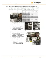
FEED ADJUSTMENTS USING THE PANDUIT ADJUSTMENT BLOCKS
As indicated in 10.3, the feed unit must be adjusted according to the ferrule size. This is accomplished by ad-
justing the forward stroke of the terminal feed (X) so that the ferrule advances properly over the crimp tooling.
Adjustment blocks (below) have been provided to make this easier for Panduit ferrules.
1.
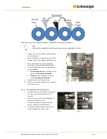
Install the ferrule strip to the end of the track,
as in Fig. 4, and remove the funnel unit if
installed.
2.
Ensure the terminal strip is fully engaged by
performing at least one cycle.
3.
Slowly lower the press ram until the feed
finger is completely pushed forward.
4.
The terminal should comes to rest over the
insulation support as shown in Fig. 5.
5.
Loosen the lock screw (1).
6.
Open the knob (2) until the adjustment block
can be inserted into the gap (X).
7.
Turn the knob (2) clockwise until the block is
snug in the gap (X). Remove the block.
8.
Tighten the lock screw (1) and cycle the press
to test. Re-adjust as necessary.
9.
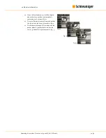
Turn the positioning knob (2) to re-position the
terminal.
a.
Counterclockwise
increases the feed and
will move the terminal further
to the
right
.
b.
Clockwise
decreases the feed and will
move the terminal further
to the left
.
X
1
2
Fig. 4
Fig. 5


