OPERATOR'S MANUAL
Gateway
Version: 27143
Subject to technical changes
Schmalenberger GmbH + Co. KG
D-72072 Tübingen / Germany
11
6 Installation
6.1
General information
For installation of FLUVO devices and systems, the respective operator’s manual applies.
27251 Converter box 3.0
27248 Control NT
27142 Luchs NT
27263 Xanas
27131 X-jet
The following section describes the gateway installation and networking options.
6.2
Mechanical installation
The gateway is intended for direct wall mounting. The device has 6xØ5.5mm through-
holes for fixed wall mounting, see Device dimensions chapter.
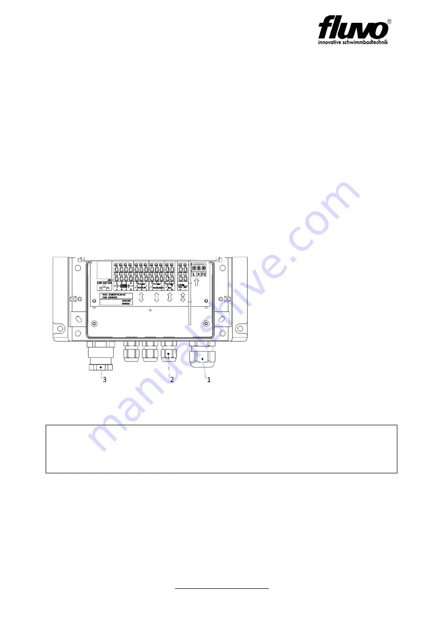
Figure 5
A cable gland [3] with a slotted
sealing insert is provided for
connecting the LAN cable.
Loosen the pressure screw and
the sealing insert. Thread the
pressure screw and sealing insert
over the assembled LAN cable.
Guide the assembled RJ45 plug
through the opening into the
terminal compartment and tighten
the pressure screw.
The cable glands [2] for
connecting the control and bus
lines are sealed with dummy
plugs as moisture protection.
To ensure the IP65 device protection class:
Make sure that
a) the cable glands in the housing are firmly tightened
b) the seal for the cable is correct.


