background image

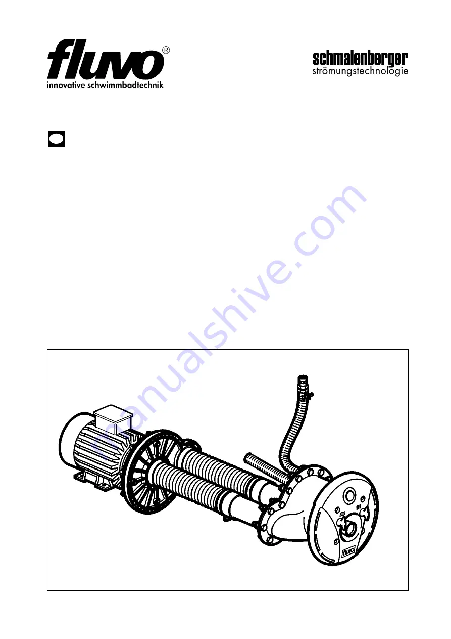
C2G rondo

D

GB

27201 - H

Operating Instructions

Transplantation of the original

Summary of Contents for fluvo C2G rondo

Page 1: ...C2G rondo D GB 27201 H Operating Instructions Transplantation of the original ...

Page 2: ...unting the installation kit Pre fabricated pool 14 4 8 Mounting the installation kit Wooden liner pool 15 4 9 Pump Kit Installation 16 4 10 Connection to the pool 16 4 11 Connection to the pump 17 4 12 Installing the switchgear cabinet 17 4 13 Non return air valve installation 18 4 14 Installation of the face plate assembly general 18 5 Electrical connections 19 5 1 Electrical Connections general ...

Page 3: ...ders or ordering spare parts 1 3 Usage Instructions The counter current unit was designed for use in private swimming pools Consequently it must not be installed in public swimming pools Neither the entire unit nor parts thereof must be used in other systems You are expressly directed to use it only in accordance with these instructions The counter current unit must not be operated beyond the para...

Page 4: ...t complies with protection class I The counter current unit is delivered as 3 assemblies 1 Pump kit 2 Assembly kit 3 Installation kit 3 1 Technical Data WS AC alternating current For more details of safety instructions please see the brochure Safety Instructions 27228 A Warning Risk of injury Warning Risk of damage This symbol warns you of dangers through mechanical effects and also warns of handl...

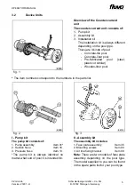
Page 5: ...ete tile pool Concrete liner pool Pre fabricated pool steel plastic or similar Wooden liner pool fig 2 fig 3 I Pump kit The pump kit consists of 1 Pump assembly Item 01 2 Suction hose Item 16 3 Pressure hose Item 13 The pump kit is always identical no matter what sort of pool it is intended for II Assembly kit The assembly kit includes 1 Face plate assembly Item 35 2 Mounting screws Item 90 3 Air ...

Page 6: ...concrete liner pools The installation kit consists of 1 Installation kit Item 20 Note The housing is concreted into the concrete wall of the pool Details of this can be found in section 4 of this manual 2 Clamp ring Item 72 3 Clamp gasket Item 32 4 Mounting screws Item 74 Note Parts 2 to 4 are delivered with the face plate assembly III Installation kit for pre fabricated pools The installation kit...

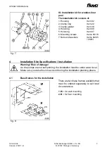
Page 7: ...2 Clamp ring Item 22 3 Clamp gasket Item 39 4 Hold ring Item 68 5 Hold ring Item 67 6 Mounting screws Items 63 74 7 Nuts and washers Items 64 65 26 83 Warning Risk of damage As the pumps are not self priming the installation must be under water level Make sure you take this into account during the installation planning phase fig 8 There are two base frames available that must be ordered separately...

Page 8: ...to the wall 200 mm 5 Be sure to cover the pump pit if it is installed in the open air 6 The position of the non return air valve L must always be over the pool water level BWSP 7 The position of the switchgear cabinet S must always be over the pool water level BWSP 8 In case of leakage from the pump a suitable water drainage must be provided fig 9 Cross sectional view of the pump pit fig 10 Top vi...

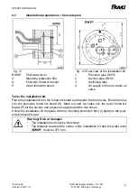
Page 9: ...and pressure supplies and the two hoses Screw the installation kit complete with the mounting protection film C tightly to the pool side formwork board fig 11 fig 12 Rear view of the installation kit BWSP Pool water level C Mounting protection film D Pool side formwork board P Outer formwork board 1 Pressure pipe DN 50 2 Suction pipe DN 65 3 Switching tube 4 Air supply to the non return air valve ...

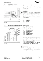
Page 10: ...Ø 205 and the mounting holes Ø 9 into the pool wall Warning Risk of damage The hold ring 62 must be used as a template For rear filling the pool ensure that there is a cavity at least the size of the dotted lines fig 14 Boring diagram Tailor the installation kit Cut the cavity Ø 260 and the mounting holes Ø 12 into the pool wall Warning Risk of damage The hold ring 68 must be used as a template Ta...

Page 11: ...e floor and the wall I to avoid the possibility of external voltage transmissions I Insulation S Screw fig 16 B Suction housing 22 Clamp ring 26 Nut 27 Distance washer 39 Clamp gasket 62 Hold ring 74 Hexagon screw 91 Installation kit Mount the clamp ring 22 with the clamp gasket 39 and the hold ring 62 to the pool wall The sealing contact faces must be clean and smooth Then mount the housing 91 on...

Page 12: ... and cut out the liner Then mount the installation kit 92 on the clamp ring 22 with the screws 74 See also detail N in fig 18 fig 17 fig 18 Detail from fig 17 B Pool wall N For details see fig 18 BWSP Pool water level 20 Installation kit 22 Clamp ring 26 Nut 27 Distance washer 39 Clamp gasket 63 Countersunk screw 67 Hold ring 68 Hold ring 74 Screw 83 Distance washer 92 Installation kit Warning The...

Page 13: ...ework R to the pump is longer than 6 m then the nominal width must be increased Suction side from DN 65 to a min of DN 80 Pressure side from DN 50 to a min of DN 65 3 Then always mount the adaptors V on the pump body fig 20 14 Return connection 17 Suction connection 20 91 92 Installation kit Stick the adaptors 14 17 to the pipe connection on the installation kit 20 91 92 Alternatively by using pip...

Page 14: ...sure side 16 suction side to the pump body Use the corresponding air pipe clamps 12 on both sides for this Warning Make sure that the connections from the body of the pump to the installation kit pipework are as nearly aligned as is possible The hose lines must always be attached to the pump on the one side compensator function see diagram fig 22 For electrical connection information regarding the...

Page 15: ... Fasten with the air pipe clamp 52 Fasten the non return air valve with the fixing bracket 56 to the pool wall or similar In the case of a ground level overflow place the non return air valve in the duct see detail B Warning To position the non return air valve also please observe the information under chapter 4 2 fig 24 A Hose coupling B Plug sleeve D Face plate assembly 21 Hose Drain the pool wa...

Page 16: ...ton put on the face plate assembly 35 this allows the pressure connection and air connection to slide into one another Fasten to the installation kit 20 with the screws 90 Warning Make sure that there is not a kink in the switching tube 21 lay it in a loop and do not shorten fig 26 C Mounting protection film 20 Installation kit 21 Switching tube 32 Clamp gasket 35 Face plate assembly 72 Clamp ring...

Page 17: ... 22 Clamp ring 35 Face plate assembly 90 Screw After connecting the air button put on the face plate assembly 35 this allows the pressure connection and air connection to slide into one another Fasten to the clamp ring 22 with the screws 90 Warning Make sure that there is not a kink in the switching tube 21 lay it in a loop and do not shorten fig 28 21 Switching tube 22 Clamp ring 35 Face plate as...

Page 18: ... 10 1995 5 The relevant DIN VDE directives 0100 and where there is a risk of explosion 0165 must also be observed If the installation is not carried out properly there is a risk of getting electric shocks Warning Compare the available power supply voltage with the details on the motor s factory plate and select the appropriate switching We recommend the use of a motor protection facility Explosion...

Page 19: ...minal box lid or enclosed circuit diagram Please be sure to observe instructions from the motor manufacturer L External conductor N Neutral conductor fig 31 Basic circuit diagram for 400 230 V three phase current Mains voltage 400 230 V for 3 current Mains power supply connection cable 5 x 2 5 mm Pump power supply cable 4 x 2 5 mm Fuse 16A passive B Control unit in the pool M Motor of the circulat...

Page 20: ...n be switched off by pressing the button again or a signal can be sent to the pump on off function fig 32 Basic circuit diagram for 400 230 V three phase current An earth leakage circuit breaker nominal fault current 30 mA must be fitted to the mains power supply Important Watch the order of the terminal bridges See the inside of the terminal box lid or enclosed circuit diagram Please be sure to o...

Page 21: ...water layer just under the surface of the water begins to flow quickly Attaching the massage set Switch off the counter current swimming unit prior to attaching the impulse massage nozzle Pull back the sliding sleeve V push the hose coupling F into the nozzle D press the sliding sleeve V against the nozzle D and pull back on the hose coupling F That causes the hose coupling to be locked in place D...

Page 22: ...tion Motor blower brushes against the blower cover Fasten the blower cover properly 2 Pump starts up heavily and slowly A current phase is missing Check supplies and fuses 3 The fuses jump out when the pump is switched on Wrong or too nimble fuses Insert passive fuses with the correct current rating 4 Motor protection switch trips Wrong setting Set correct current value 10 see Technical Data 5 Cen...

Page 23: ...k of damage Make sure you have protected the whole swimming complex adequately against frost Observe the instructions issued by the manufacturer of the pool Empty all the water out of the pool or let the water out at least until it is below the level of the jet head Switch off the master switch fig 34 07 O Ring 11 Plug screw Screw out the plug screw 11 and drain the water Warning Risk of damage Ma...

Page 24: ...current unit are kept clean The gaskets on the motor shaft must be checked at regular intervals at least once a year by a trained engineer If necessary they must be replaced by original spare parts 9 3 Repairs For any necessary repairs to the counter current unit please observe the instructions for installation and start up in this manual Use exclusively original spare parts when carrying out repa...

Page 25: ... IEC 38 400 230 V 02 3 89125 Schaltkasten Dreh strom Switchgear cabinet 3 phase 1 3 kW IEC 38 400 230 V 03 R47505 Spiralgehäuse Spiral housing 1 04 21140 Gleitringdichtung Mechanical seal 1 05 51066 Unterlegscheibe Distance washer 1 06 1 51021 Laufrad Impeller 1 1 9 kW Ø 110 06 2 51022 Laufrad Impeller 1 3 0 kW Ø 125 07 24133 O Ring O ring 2 10 0 x 2 0 08 56033 Laufradschraube Impeller cap screw 1...

Page 26: ... Gehäuse Housing 1 43 1 10401 Schneidschraube Socket head cap screw 3 5 5 x 25 43 2 56036 Gehäuse Housing 1 44 13154 Zylinderstift Parallel pin 1 45 55602 Welle f Luftregelung Air regulator shaft 1 46 22008 Flachdichtung Clamp gasket 1 16x08x3 0 47 51098 Bundhülse Shaft collar 1 48 57952 Zentrierhülse Nozzle case sleeve 1 49 56682 Gewindehülse Threaded sleeve 1 50 23073 Dichtung Gasket 2 51 56681 ...

Page 27: ...inschubsatz Insert set 1 77 92298 Einbauelemente Fittings 1 78 92299 Einbauelemente Fittings 1 83 12392 Unterlegscheibe Distance washer 8 A 8 90 1 10880 Linsensenkschraube Face plate screw 4 M8x100 90 2 10779 Linsensenkschraube Face plate screw 4 M8x70 90 3 10539 Linsensenkschraube Face plate screw 4 M8x45 91 93129 Einbausatz Installation kit 1 92 93128 Einbausatz Installation kit 1 93 10530 Sechs...

Page 28: ...Drawing 124 C2G rondo Version 27201 H Schmalenberger GmbH Co KG D 72072 Tübingen Germany Concrete tile pool 8245 28 ...

Page 29: ...Drawing 125 C2G rondo Version 27201 H Schmalenberger GmbH Co KG D 72072 Tübingen Germany 8246 Concrete liner pool 29 ...

Page 30: ...Drawing 126 C2G rondo Version 27201 H Schmalenberger GmbH Co KG D 72072 Tübingen Germany 8247 Prefabricated pool 30 ...

Page 31: ...Drawing 127 C2G rondo Version 27201 H Schmalenberger GmbH Co KG D 72072 Tübingen Germany 8248 Wood liner pool 31 ...

Page 32: ...technologie Telefax 49 0 7071 70 08 10 Im Schelmen 9 11 Internet www fluvo de D 72072 Tübingen Germany E Mail info schmalenberger de 2020 Schmalenberger GmbH Co KG All rights reserved This document is subject to change without notice Typ C2 rondo Version 27201 H ...

Reviews: