Operator`s Manual
XANAS
®
Version: 27258-E
Schmalenberger GmbH + Co. KG
D-72072 Tübingen / Germany
9
3.2.
Pipe dimensioning
3.2.1.
Flow speeds
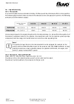
To prevent impacts due to acceleration or delay, the flow speed should be kept uniform in the pipelines.
The following approximate values are cited in the relevant sources (for pipework up to 6m, the following
exemplary recommendations apply):
Empfohlene Flow speed
(by Water)
42 m³/h
48 m³/h
60 m³/h
72 m³/h
Suction line
1,0
–
1,5 m/s
DN 100
DN 125
DN 125
DN150
Pressure line
2,5
–
3,0 m/s
DN 65
DN 80
DN 100
DN 100
An economical speed is the determining factor for the dimensioning. It is derived from the optimum of
the total of investment costs for the pipeline, the investment costs for the machine system (pumps,
compressor) and the energy and maintenance costs over the entire operating time.
Note!
For pipelines longer than 6m, the nominal width must be enlarged, for example on the
suction side from DN100 to DN125 and on the pressure side from DN80 to DN100. To keep
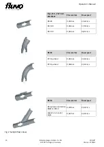
pipeline resistances as low as possible, always use pipelines with bends, not angles, and
use 45° T-pieces instead of 90° T-pieces.
3.2.2.
Flow Losses - Pipes and Elements
Water, 48 m³/h; turbulent flow; roughness value: 0.1 mm
Flow losses in the entire pipeline (pressure and suction side) must be noted.
Flow losses must be keptlow in the components that are used.


