Installation
44 / 72
EN-US · 30.30.01.02084 · 02 · 12/20
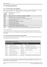
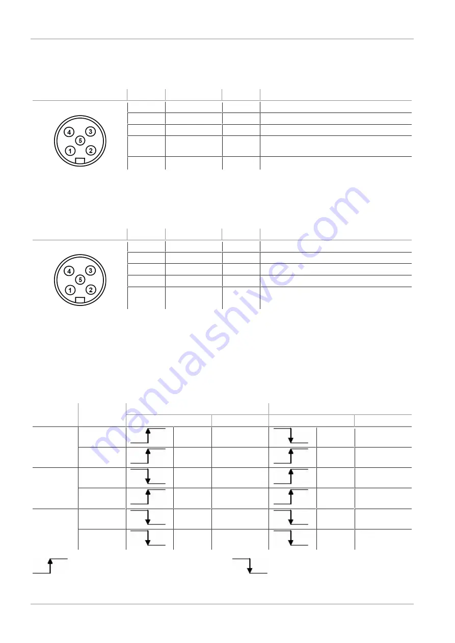
9.4.1 PIN Assignment
PIN assignment, 5-pin M12 connector
M12 connector
PIN
Wire color
1)
Symbol
Function
1
Brown
U
S/A
Supply voltage for sensors/actuators
2
White
IN1
“Suction” signal input
3
Blue
GND
S/A
Ground for sensors/actuators
4
Black
OUT
“Part Present” check signal output (H2/
h2)
5
Gray
IN2
“Blow off” signal input
1)
When using Schmalz connection cable part no. 21.04.05.00080
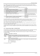
9.4.2 PIN Assignment in IO-Link Mode
PIN assignment, 5-pin M12 connector
M12 connector
PIN
Wire color
1)
Symbol
Function
1
Brown
U
S/A
Supply voltage for sensors/actuators
2
White
—
—
3
Blue
GND
S/A
Ground for sensors/actuators
4
Black
C/Q
IO-Link communication
5
Gray
—
—
1) When using Schmalz connection cable part no. 21.04.05.00080
9.5 Start of Operations
A typical handling cycle is divided into the following three phases: pickup, blowoff and idle.
To check whether sufficient vacuum has built up, the limit value H2 is monitored by an integrated vacuum
sensor during suction and output to the higher-level controller via OUT.
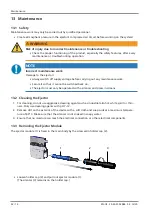
Phase
Switching
step
NC version
NO version
Signal
Status
Signal
Status
1
1
IN1
Suction ON
IN1
Suction ON
2
OUT
Vacuum > H2
OUT
Vacuum > H2
2
3
IN1
Suction OFF
IN1
Suction OFF
4
IN2
Blow off ON
IN2
Blow off ON
3
5
OUT
Vacuum <
(H2-h2)
OUT
Vacuum <
(H2-h2)
6
IN2
Blow off OFF
IN2
Blow off OFF
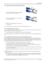
Signal status changes from inactive to active.
Signal status changes from active to in-
active.


