Product description
EN-US · 30.30.01.01963 · 00 · 05/19
13 / 52
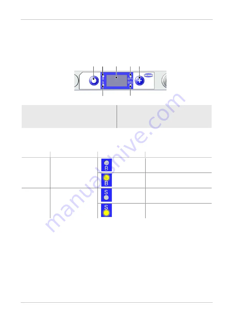
3.5 Controls and Displays in Detail
The ejector is fitted with the following elements to ensure simple operation:
•
2 buttons on the foil keypad
•
A 3-digit display
•
4 light-emitting diodes (LEDs) as status indicators
1
2
3
4
5
7
6
1
MENU BUTTON
2
LED B for blow off state
3
Display
4
LED for switching point limit value SP1
5
UP BUTTON
6
LED for switching point limit value SP2
7
LED S for suction state
—
—
Definition of the LED Indicators
The “suction” and “blow off” process states are each assigned an LED.
Item
Meaning
State
Description
2
Blow off LED B
OFF
Ejector not blowing off
Lit up
Ejector blowing off
7
Suction LED S
OFF
No suction from ejector
Lit up
Suction from ejector
The LEDs for the SP1 and SP2 switching points (limit values) indicate the current level of the system vac-
uum relative to the configured limit values. Their behavior is independent of the control function and the
assignment of the output.


