Installation
82 / 94
EN-US · 30.30.01.02237 · 00 · 04/20
8.4.1 Instructions for Start of Operations
To operate the Compact terminal SCTSi, the supply voltage and at least one communication line must be
connected.
The integrated switch can be used to loop through the communication line.
The supply voltage for the sensors (U
S
) and the supply voltage for the actuators (U
A
) are electrically iso-
lated and can come from different sources.
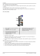
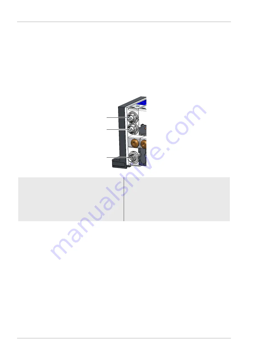
8.4.2 Bus module
3
1
2
1
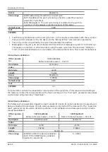
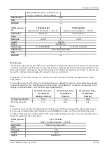
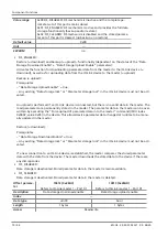
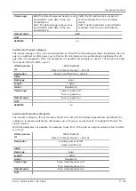
M12-L electrical connection plug for volt-
age supply
Labeled with X03 on bus module
2
M12-D electrical connection socket for
Ethernet Port X02 (straight [1:1])
Labeled with X02 on bus module
[EtherCAT: OUT port]
3
M12-D electrical connection socket for
Ethernet Port X01 (crossover [x])
Labeled with X01 on bus module
[EtherCAT: IN port]
ü
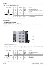
Prepare the connection cable.
1. Fasten the connecting cable on the SCTSi to the electrical connection (1) with 5-pin M12 plug in L-
coded design; max. tightening torque = hand-tight.
2. At least one Ethernet cable also needs to be connected to the D-coded M12 sockets at connection (2)
or (3).
Observe the following connection instructions:
•
The SCTSi can be operated only via Ethernet communication. This requires corresponding hardware
components (master).
•
The data cable must be shielded. The cable shield must be equipotentially bonded.
•
The functional ground of the voltage supply cable must be equipotentially bonded.
•
The SCTSi is designed to supply sensors and actuators with potential separation.

