INSTALLATION
28 | EN
www.schmalz.com
30.30.01.00176/01
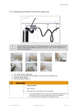
Procedure (with illustrative figures):
1.
Clamp the rotary union in a vise above the
screws on the tube holder (Image 1).
2.
Remove the protective cap from the end of
the threads on the hose clamp.
3.
Remove the hose clamp from the lift tube
using an open-ended wrench.
4.
Remove the adhesive tape from the lift tube.
5.
Rotate the lift tube and remove from tube
holder (Image 2).
6.
Cut the lift tube at the desired position using
a box cutter; cut off the wire spiral using the
bolt cutter.
7.
Apply multipurpose grease to the rotary
union (thread) (to facilitate mounting of the
lift tube).
8.
Twist the lift tube all the way back onto the
threads of the rotary union. Twist on the lift
tube far enough so that it completely covers
the threads of the rotary union (Image 3).
The grounding is ensured by the metal contact
between the wire spiral and rotary union.
9.
Wrap insulating tape around the lift tube to
completely seal the cover of the rotary union
(wrap adhesive tape approx. twice around
the entire lift tube) (Image 4 and 5)
10. Pull the hose clamp onto the lift tube and
tighten it using a torque wrench with 10 Nm
(Image 6)
11. Ensure that both hose clamps are
connected with equipotential bonding (see
chapter 5.2.2).
12. Fit the protective cap back onto the end of
the threads on the hose clamp (Image 7)
13. Earth the lift tube on the rotary union (upper
end, figure 8).
14. Earth the lift tube on the operator handle
(lower end, figure 9).
Figure 1
Figure 2
Figure 3
Figure 4
Figure 5
Figure 6
Figure 7
Figure 8
Figure 9

