background image

SAFETY INSTRUCTIONS 

12 |   EN 

www.schmalz.com 

30.30.01.00176/01 


The operator must ensure that any people charged with installing, starting operations 
on, operating, maintaining or repairing the tube lifter: 


Have received special training for performing work in potentially explosive 
atmospheres  


Are at least 18 years of age  


Are mentally and physically fit for the task 


Have been trained in operating and maintaining the tube lifter 


Have read and understood the operating instructions 


Can be expected to reliably perform the tasks assigned to them  

The operating instructions must be accessible at all times. 
The type plate and warning signs must be legible. 
The operator is obligated to perform a risk assessment for the ambient conditions at 
the installation location.


The tube lifter must be installed, maintained and repaired only by qualified specialist electricians and 
mechanics.  

Qualified specialist = 

an employee who has received technical training and has the knowledge and 

experience

—including knowledge of corresponding regulations—necessary to enable him or her to 

recognize possible dangers and implement the appropriate safety measures while performing tasks. 

1.9  Installation location/workplace requirements 

1.9.1  Installation location requirements 


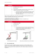
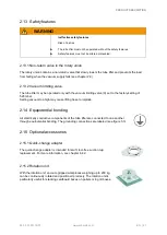
DANGER


Usage in impermissible potentially explosive zones 


Risk of explosion 

► 


► 


► 

► 

► 

The tube lifter is classified as follows according to ATEX directive 2014/34 EU: 

II 2G c IIB T6 
II 2D c T85°C


As per ATEX directive 1999/92 EC, the operator is obligated to ensure that the 
tube lifter is suitable for its task. The manufacturer accepts no liability for 
damages caused by the use of the tube lifter in areas with a high risk of 
explosion. 

Integrate the tube lifter into the lightning protection concept at the location of 
use. 

Observe the applicable national regulations.  

If you have doubts, consult with the manufacturer before starting operations. 


The tube lifter must not be operated under the following conditions: 


Areas with acidic or alkaline media or in contaminated atmospheres 


In moist, wet, oily, icy, dirty or dusty environments, or in any other environments that might 
reduce the level of friction 


Outside the temperature range of +0° C to +40° C  


Protect the tube lifter from direct UV exposure (due to the service life of the plastic parts).


If you have doubts, consult with the manufacturer before starting operations. 

Summary of Contents for Jumbo Sprint 45

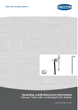
Page 1: ...www schmalz com Ergonomic Handling Solutions EN Operating and Maintenance Instructions Vakuum Tube Lifter JumboSprint EX Ejektor 30 30 01 00176 01 04 2017...

Page 2: ...ains the rights established thereby Reproduction of the contents in full or in part is only permitted within the limits of the legal provisions of copyright law Any modifications to or abridgments of...

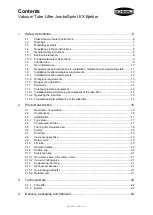
Page 3: ...ersonal protective equipment 14 1 12 1 Installation decommissioning and disposal of the tube lifter 14 1 12 2 Operating the tube lifter 15 1 12 3 Troubleshooting maintenance of the tube lifter 15 2 Pr...

Page 4: ...st 33 6 Operation 34 6 1 General safety instructions 34 6 1 1 Ejector 34 6 1 2 Tube lifter 35 6 2 Checks Before Starting Work 36 6 3 What to do in an emergency 36 6 3 1 Production of an ignition sourc...

Page 5: ...SAFETY INSTRUCTIONS 30 30 01 00176 01 www schmalz com EN 5 9 5 Spare parts 50 9 6 Circuit Diagram 50 9 7 Expert approval 50 10 Decommissioning and Disposal 51 10 1 Decommissioning 51 10 2 Disposal 51...

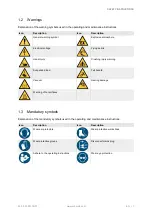
Page 6: ...er of a risk that could result in death or serious injury if it is not avoided WARNING Type and source of danger Consequence Remedial action Caution This warning informs the user of a risk that could...

Page 7: ...Electrical voltage Flying debris Hand injury Crushing injury warning Suspended load Fall hazard Vacuum Hearing damage Warning of hot surfaces 1 3 Mandatory symbols Explanation of the mandatory symbol...

Page 8: ...r crane systems column mounted jib cranes etc 1 5 General safety instructions 1 5 1 Explosion protection DANGER Ignition sources Risk of explosion When used in potentially explosive atmospheres Preclu...

Page 9: ...Personal injury damage to plants systems All safety features must be in proper working order Safety features must not be altered or disabled The tube lifter must be in perfect working order and must...

Page 10: ...apacities see chapter 3 The tube lifter must be used only when hung from the rotary union suspension eye Observe the type plate and load capacity sticker DANGER Unsuitable crane system Risk of fatal i...

Page 11: ...nger of imploding WARNING Handling a load with more than on tube lifter Danger of fatal injuries due to falling objects The load must be handled only with one tube lifter The manufacturer must be cons...

Page 12: ...sible dangers and implement the appropriate safety measures while performing tasks 1 9 Installation location workplace requirements 1 9 1 Installation location requirements DANGER Usage in impermissib...

Page 13: ...up 1 10 Danger zone definition Danger areas in red shading The areas directly above and below the tube lifter and load The area around the tube lifter and load The crane system danger area DANGER Dang...

Page 14: ...s therefore important that no polluted or contaminated ambient air particle size 5 m is sucked in Risk of eye injury Manufacturer s recommendation Operate the tube lifter with dust filters at all time...

Page 15: ...g on the load sturdy work gloves in accordance with EN 388 safety category 2133 or better 1 12 3 Troubleshooting maintenance of the tube lifter Protective work shoes in accordance with EN 20345 safety...

Page 16: ...n cups via the supply hose and lift tube The vacuum keeps the load attached to the suction cup Controlled leakage of the vacuum in the lift tube is used for lifting and lowering 2 2 Components 6 1 7 6...

Page 17: ...anty claims or placing other inquiries regarding the lifting device always provide the device type the part number the order number and the year of manufacture 2 4 Compressed air tube The compressed a...

Page 18: ...ed air OFF Close valve Pull the red ball knob 8 2 WARNING Vacuum failure Falling load Pull the red ball knob only if no load is suspended from the tube lifter 2 6 Ejector Ejector 1 produces vacuum for...

Page 19: ...ry union of the tube lifter The metal support spindle on the vacuum supply hose acts as an earthing lead for installation instructions see chapter 5 2 2 2 9 Rotary union The rotary union 4 connects th...

Page 20: ...e with EN 14238 to verify that the suction cup is suitable for the load to be lifted see chapter 5 5 suction cups and their applications Single suction cups Glued cardboard boxes sheets furniture bodi...

Page 21: ...um limiting valve 9 set to the factory setting of 520 mbar Setting vacuum too high may cause lifting hose to implode 2 14 Equipotential bonding All electrically conductive components of the tube lifte...

Page 22: ...temperature 0 C to 40 C Maximum operating medium temperature 40 C 3 1 2 Ejector Operating pressure 4 to 6 bar Air consumption 900 to 1 250 Nl min Max sound level approx 70 dB A Operating medium on co...

Page 23: ...nothing is missing 4 1 3 Report damage Following delivery of the shipment damage caused by defective packaging or in transit must be reported immediately to the carrier and J Schmalz GmbH 4 2 Packagi...

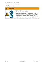
Page 24: ...ng Risk or personal injury or property damage Ensure the hoists and slings used have the necessary specifications Ensure that any personnel involved in transporting or unloading with lifting devices o...

Page 25: ...rt particles are able to enter compressed air supply system during installation 2 Connect compressed air hose 2 to compressed air connection on ejector and secure this using hose clamp 3 Lay hose asse...

Page 26: ...of crane jib Never carry out work without using end buffer This can result in lifting unit falling off 3 Connect compressed air hose 2 to pressurised connection point of ejector 1 and secure this usin...

Page 27: ...all times when the lift tube is shortened The lift tube 5 should be shortened at the rotary union 4 or upper end Take down the tube lifter to shorten the lift tube Tube lifter stroke approx 0 7 x leng...

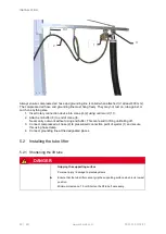
Page 28: ...threads of the rotary union Twist on the lift tube far enough so that it completely covers the threads of the rotary union Image 3 The grounding is ensured by the metal contact between the wire spira...

Page 29: ...s see the figures 1 Lay out the vacuum supply hose 2 Cut into the hose wall material for approx 30 mm along the support spindle 3 Strip the support spindle 4 Bend the support spindle 90 WARNING Fallin...

Page 30: ...es should be installed on all moving parts 5 3 1 Grounding points Provide all connection points for grounding wires with a low resistance grounding The connection points are labeled Ensure that any or...

Page 31: ...ers 4 Contact washer 5 Spring washer 6 Sticker for marking grounding If there is no thread use a self locking hexagonal nut on the other side 5 3 2 Resistance measurement Measure the total resistance...

Page 32: ...the resistance where necessary 5 4 Setting the hovering position On the tube lifter you can set the hovering position with and without a load to a working height adapted to the activity If the hoverin...

Page 33: ...clockwise hovering position is lowered Turn counterclockwise hovering position is raised ATTENTION Hovering position at the end stop in the top position Damage to the ejector High energy consumption W...

Page 34: ...ntially explosive atmospheres Has been instructed on how to operate the tube lifter Has read and understood the operating instructions See chapter 1 8 If faults occur during operation switch off the t...

Page 35: ...ns Risk of injury when The load falls The operator handle jolts upward uncontrollably Ensure that vacuum generation cannot be switched off during handling Ensure that there are no loose parts on the l...

Page 36: ...aces open flames hot gases or liquids mechanically produced sparks adiabatic compression shock waves exothermic chemical reactions thermal reactions the spontaneous combustion of dust electric arcs or...

Page 37: ...d sealing foams 1 The service life of suction sealing lips and sealing foams can be extended by putting the sealing on cleanly and avoiding lateral loads 2 Check the resistance of foams and sealing li...

Page 38: ...ing 1 Switch off the vacuum generator 2 Insert the suction cup into the operator handle A and rotate the suction cup in direction B until the latching bolt 5 engages in the end position in the designa...

Page 39: ...osit Load 2 Hold the operator handle firmly 3 Switch on the vacuum generator 4 Open the ball valve of the compressed air off switch by pulling the black ball knob 8 1 6 6 Lifting the load WARNING Tube...

Page 40: ...ravity of the load the lift tube will wear prematurely Ensure that the workpiece is lifted by the center of gravity of the load 1 Position the suction cup directly above the load 2 Press the operator...

Page 41: ...ion 6 8 Setting down the load WARNING Load deposited unsafely Risk of injuries Before releasing the load ensure that it cannot slip or tilt CAUTION Uncontrolled tube lifter movement Risk of injuries A...

Page 42: ...n a safe position on the crane system Do not set the tube lifter down on the workpiece CAUTION Misuse Risk of injuries Ensure that unauthorized persons cannot put the tube lifter into operation ATTENT...

Page 43: ...m the lift tube and operator handle ATTENTION Incorrect storage of the tube lifter Damage to the suction plates The effects of ozone light especially UV heat oxygen humidity as well as mechanical infl...

Page 44: ...lution Preventive measures Required vacuum not attained Insufficient compressed air supply Examine the supply hose and tube lifter for cracks Check gripping mechanism Clean dust filter cartridge and o...

Page 45: ...ith the manufacturer While the vacuum generator is in use the tube lifter operator handle hangs in the upper block position even without a load and cannot be lowered or can only be lowered slowly by o...

Page 46: ...ance repair work As a basic principle following repair or maintenance work check the safety features see chapter 9 1 and equipotential bonding see chapter 5 3 9 1 Inspecting safety features Check the...

Page 47: ...as it been cleaned See chapter 9 3 2 X X Is the lift tube in good condition not porous no worn sections no holes and therefore sealed X X Is the lift tube attached properly Screw clip in the correct p...

Page 48: ...accident prevention inspection been completed UVV test badge in Germany X 9 3 Dust filter 9 3 1 Ejector dust filter DANGER Replacing the filter cartridge while vacuum is applied Risk of injuries Befo...

Page 49: ...lose the cover To blow out the unit set a pipe on a compressed air gun that is bent at the end by approx 90 The pipe must be long enough to reach the bottom of the cartridge 9 3 2 Operator handle dust...

Page 50: ...al circuit diagram see the appendix 9 7 Expert approval Please observe the national accident prevention laws and regulations Make sure that inspections and tests are arranged for the required times an...

Page 51: ...d safely see chapter 1 5 Store the tube lifter to prevent it from being damaged 10 2 Disposal 1 Shut down the tube lifter 2 Detach and dispose of the suction plates 3 Release the hose clamps and remov...

Page 52: ...operating instructions and CAD data and get comprehensive information about our products and services www schmalz com dokumentationen How to videos In short easy to understand videos we explain the e...

Reviews: