S
CHMALZ
SCP
I
/
SMP
I
GB - 2
1 S
TART
-
UP
Electrical connection
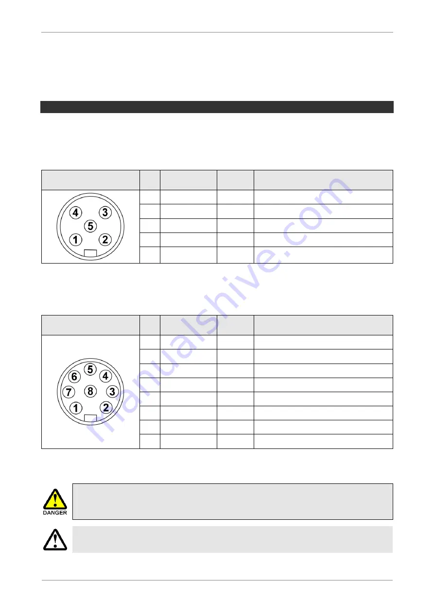
The electrical connection of the ejector is made using a 5-pin or 8-pin M12 male connect-
or. The pin assignment of the connector is as follows:
M12
5-
PIN MALE CONNECTOR
Connector
Pin Core colour
1)
Symbol Function
1
Brown
U
SA
Power supply
2
White
IN1
Suction signal input
2)
3
Blue
Gnd
SA
Ground
4
Black
OUT
Parts control signal output
5
Grey
IN2
Blow-off signal input
3)
1)
When Schmalz connection line item no. 21.04.05.00080 is used
2)
NO version: Vacuum OFF, NC version: Vacuum ON, IMP version: Vacuum ON only
3)
NO/NC version: Blow off ON/OFF, IMP version: Vacuum OFF and blow off ON/OFF
M12
8-
PIN MALE CONNECTOR
-
VERSION WITH POTENTIAL ISOLATION
(PT)
BETWEEN
U
S
AND
U
A
Connector
Pin Core colour
1)
Symbol Function
1
White
U
A
Power supply for actuator
2
Brown
U
S
Power supply for sensor
3
Green
Gnd
A
Actuator ground
4
Yellow
IN1
Suction signal input
2)
5
Grey
OUT
Parts control signal output
6
Pink
IN2
Blow-off signal input
3)
7
Blue
Gnd
S
Sensor ground
8
Red
-
Not connected
1)
When Schmalz connection line item no. 21.04.05.00079 is used
2)
NO version: Vacuum OFF, NC version: Vacuum ON, IMP version: Vacuum ON only
3)
NO/NC version: Blow off ON/OFF, IMP version: Vacuum OFF and blow off ON/OFF
The ejector may only be operated via power supply units with protected
extra-low voltage (PELV). The system must incorporate safe electrical cut-
off of the power supply in compliance with EN60204.
The plug connectors may not be connected or disconnected when the system is
live.
Summary of Contents for SCPi
Page 14: ...SC H MA L Z SCPI SMPI DE 13 Betriebszustände ...
Page 27: ...SC H MA L Z SCPI SMPI GB 13 Operating modes ...
Page 40: ...SC H MA L Z SCPI SMPI FR 13 Etats de fonctionnement ...
Page 53: ...SC H MA L Z SCPI SMPI ES 13 Estados de funcionamiento ...
Page 66: ...SC H MA L Z SCPI SMPI IT 13 Stati di funzionamento ...
Page 68: ......


