Description of the Ejector
EN-US · 30.30.01.01961 · 00 · 06/19
13 / 68
4 Description of the Ejector
4.1 Suction of the Workpiece (Vacuum Generation)
The ejector is designed for vacuum handling of airtight parts in combination with suction systems. The
vacuum is generated in a nozzle according to the Venturi principle, i.e. by using suction generated by the
flow of accelerated compressed air. Compressed air is channeled into the ejector and flows through the
nozzle. A vacuum is generated immediately downstream of the motive nozzle; this causes the air to be
sucked through the vacuum connection. The air and compressed air that have been removed by the suc-
tion exit together via the silencer.
The venturi nozzle on the ejector is activated and deactivated using the suction command:
•
In the NO (normally open) variant, the venturi nozzle is deactivated when the suction signal is re-
ceived.
•
In the NC (normally closed) variant, the venturi nozzle is activated when the suction signal is re-
ceived.
An integrated sensor records the vacuum generated by the venturi nozzle. The exact vacuum level is
shown on the display and can be read from the IO-Link process data.
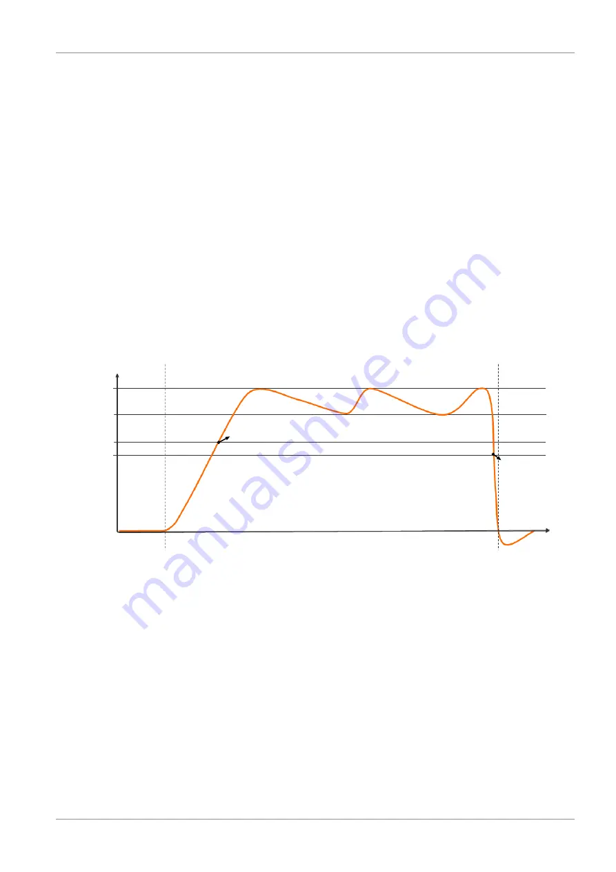
The diagram below shows the vacuum curve for when the air saving function is activated:
Vacuum
[mbar]
Vacuum on
Time [s]
SP1
SP2
rP1
rP2
OUT=on
OUT=off
The ejector has an integrated air saving function and automatically regulates the vacuum in suction
mode:
•
The electronics switch the venturi nozzle off as soon as the vacuum limit value set for switching
point SP1 is reached.
•
When objects with airtight surfaces are picked up, the integrated non-return valve prevents the vac-
uum from dropping.
•
If leakages cause the system vacuum to drop below the limit value configured for the switching
point rP1, the venturi nozzle is switched back on.
•
The OUT output is set once a workpiece is picked up securely, based on the vacuum value. This en-
ables the further handling process.


