background image

Operating Manual 

V

ACU

M

ASTER

 Multi-Serie 

Chapter 2 

Technical Data


J. Schmalz GmbH 
Aacher Straße  29 
D  - 72293 Glatten 
Tel  +49 +7443 / 2403 - 0 
Fax +49 +7443 / 2403 - 259 
http://www.schmalz.de 
e-mail: schmalz@schmalz.de 


BA 30.30.01.00221-00 

Status 03.2013 

Page 7/18 

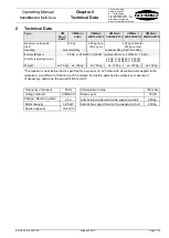
Technical Data 

Type 

VM 

M

ULTI


400-1 

VM M

ULTI


400-2 

VM M

ULTI


400/150-90°-1 

VM M

ULTI


400/300-90°-1 

VM M

ULTI


400/300-90°-2 

VM M

ULTI


400/300-90°-8 

Maximum permissible 
load* 

400 kg 

400 kg horiz. 

150 kg vert. 

400 kg horizontal 

300 kg vertical 

Handling 

horizontal lifting 

horizontal lifting & 90°-swivelling 

Electric (Blower) 

50 Hz: 3~ 230/400 V; 0,95 kW   (optional 60 Hz: 3~ 255/440 V; 1,6 kW) 

Electric (swivelling motor) 


50 Hz: 3~ 230/400 V; 0,25 kW 
60 Hz: 3~ 250/440 V; 0,25 kW 

Weight 

ca. 75 kg 

ca. 105 kg 

ca. 105 kg 

ca. 130 kg 

ca. 135 kg 

ca. 120 kg 


*The maximum permissible load is specified for a vacuum of 

–125 mbar with all suction pads applied to the 

workpiece. A coefficient of friction of µ=0.5 between the suction pads and the workpiece is assumed  
(if necessary, determine the actual friction factor!!). 


Frequency of network 

50 Hz 

  Underpressure max. 

180 mbar 

Voltage / Blower 

230/400 V 

  Noise Level 

72 dB 

Voltage / Reversing valve 

24 V 

  Admissible tensile load on the suspension bolt 

600 kg 

Motor capacity 

0,95 kW 

  Admissible support load on the suspension bolt 

600 kg 

Suction capacity 

168 m³/h 


Summary of Contents for VacuMaster Multi 400-1

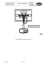
Page 1: ...A 30 30 01 00221 00 J Schmalz GmbH Aacher Stra e 29 D 72293 Glatten Tel 49 7443 2403 0 Fax 49 7443 2403 259 http www schmalz de e mail schmalz schmalz de Status 03 2013 Page 1 18 Please keep this manu...

Page 2: ...evices 2 Technical Data 3 Description 3 1 Components of the Lifting Device 3 2 Blower with Reversing Device 3 3 Swivelling Unit only MULTI 90 3 4 Controls 3 5 Suction boxes pads 4 Installation 4 1 Gen...

Page 3: ...Operating Manual Blower Gebl K10 DG 14 Spare Part List Blower Gebl K10 DG 14 Electrical Connection Diagram EU Conformity Declaration Special features The unit is equipped with the following special f...

Page 4: ...he operating instructions and especially the chapter Safety therein Your company must ensure by internal measures that the operators of the lifting device are properly trained that they have read and...

Page 5: ...f possible If this is not possible immediately leave the dangerous area near the load Danger The device generates a very strong suction which can draw in hair and clothing Do not look into the suction...

Page 6: ...Check all suction hoses and clamps for proper mounting if necessary retighten the clamps Checking the warning signal Switch on the lifting device Place it on a board suck the board Danger Attention O...

Page 7: ...Blower 50 Hz 3 230 400 V 0 95 kW optional 60 Hz 3 255 440 V 1 6 kW Electric swivelling motor 50 Hz 3 230 400 V 0 25 kW 60 Hz 3 250 440 V 0 25 kW Weight ca 75 kg ca 105 kg ca 105 kg ca 130 kg ca 135 k...

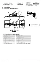
Page 8: ...2013 Page 8 18 3 Description 3 1 Components of the Lifting Device The parts with safety function appear in bold type Pos Description Pos Description 1 Blower 8 Switch box 2 Reversing Device 9 Clampin...

Page 9: ...00221 00 Status 03 2013 Page 9 18 The parts with safety function appear in bold type Pos Description Pos Description 1 Blower 9 Clamping lever 2 Reversing Device 10 Star grip 3 Swivelling Unit 11 Ball...

Page 10: ...A springloaded brake stops the swivelling In the beginning a thin grease residue may show on the drive shaft and air relief valve This is normal and no reason to worry 3 4 Controls The controls are mo...

Page 11: ...the supply cable with plug from the control box Connect the cable to the power supply of the crane or hoist according to local regulations This job must be done by a qualified electrician Be sure that...

Page 12: ...oads when the vacuum is below 0 125 bar When the pointer of the pressure gauge moves into the red danger zone below 0 125 bar put the load down immediately When the horn blows put the load down immedi...

Page 13: ...n activating a Release button Crushing hazard Hold both Release buttons 3 and raise the lifting device 5 5 Switch on off the back suction pad row To remove boards from racks the back suction pad row c...

Page 14: ...does not suck wrong rotation direction Check and correct connection reversing unit do not work Check control reverse jammed clean it filter get choked Replace clean filter Blower dropped out power on...

Page 15: ...n swivelling devices gearwheel cover securely fitted X X Inspect and maintain the blower and reversing unit as described in the operating instructions See operating instructions for blower and reversi...

Page 16: ...wivel Unit only MULTI 90 The oil in the gearbox of the swivel head must be changed after 10 000 operating hours or after three years whichever occurs sooner Oil capacity 0 2 litres To change the oil f...

Page 17: ...e for leaks once per month Place the suction pads on an airtight smooth surface such as a sheet of metal Switch on the vacuum blower and suck on the workpiece A vacuum of at least 0 15 bar has to be r...

Page 18: ...x load must not be exceeded 9 Guarantee spare and consumable parts This equipment is guaranteed in accordance with our General Conditions of Business This also applies to spare parts where these are o...

Reviews: