background image

Description of Functions

EN-US · 30.30.01.00956 · 03 · 05/22

27 / 44

The condition monitoring and diagnostics modes cannot be activated simultaneously for both
switching points. That means that when a switching point is already parameterized to C.no,
C.nc, D.no or D.nc, the other can only adopt the modes H.no, H.nc, F.no or F.nc.

The version P10 is purely a pressure switch and therefore does not offer condition monitoring
mode to monitor the vacuum leakage.

With the version VP8 with combined vacuum/pressure measurement range, the switching points react ac-
cording to the position of their “upper” switching point SPx/FHx as a pressure switch or vacuum switch.
Values are considered “bigger” when they are further from zero and as “smaller” when they are closer to
zero.

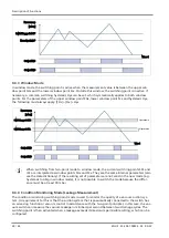
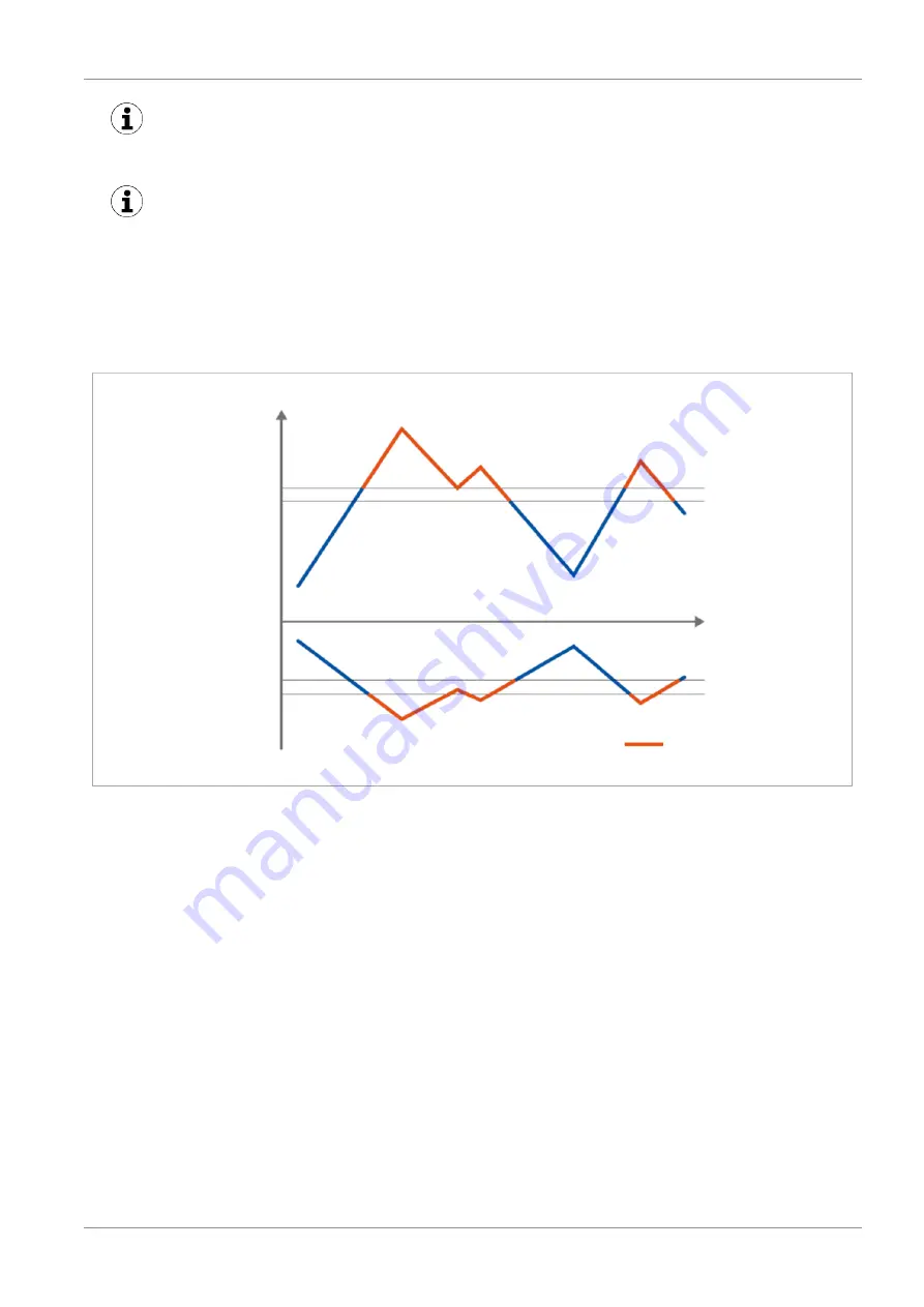
The following diagram shows the switching point behavior using the two-point mode as an example:

Pressure [bar]

Switching point (SP)

Reset point (rP)

Reset point (rP)

Switching point (SP)

Vacuum [mbar]

Vacuum range
SP < rP

Pressure range
SP > rP

Switching point active

Time (t)

9.4.2   Two-Point Mode

The two-point mode is a threshold switch with hysteresis.

When the measurement value increases, the switching point will be active when the switch-on threshold
SPx is reached and remains on until it falls below the reset threshold rPx. The following must always apply
for switching thresholds and reset thresholds: |SPx| > |rPx|. The hysteresis is therefore defined by the differ-
ence |SPx – rPx|.

Summary of Contents for VSi D Series

Page 1: ...Vacuum Pressure Switch VSi VSi D Operating instructions WWW SCHMALZ COM EN US 30 30 01 00956 03 05 22...

Page 2: ...ished thereby Repro duction of the contents in full or in part is only permitted within the limits of the legal provisions of copyright law Any modifications to or abridgments of the document are proh...

Page 3: ...al Data 10 4 1 General Data 10 4 2 Electrical Data 10 4 3 Mechanical Data 11 4 4 Factory Settings 12 5 Installation 13 5 1 Mounting 13 5 2 Electrical Connection 13 6 IO Link Commissioning 15 7 Interfa...

Page 4: ...itching Point Settings 30 9 7 Display Screen 31 9 8 Access Rights 31 9 9 Device Identification 32 9 10 System Monitoring and Diagnostics 33 9 11 System Commands 34 10 Help with Malfunctions 35 11 List...

Page 5: ...roduct 1 For problem free and safe operation follow the instructions in the documents 2 Keep the technical documentation in close proximity to the product The documentation must be ac cessible to pers...

Page 6: ...owing points The personnel must be commissioned for the activities described in these operating instructions The staff must be at least 18 years of age and physically and mentally capable The operatin...

Page 7: ...n the sensor and actuator voltage 4 Wear the required personal protective equipment PPE when working in the danger zone CAUTION Noise pollution from leakage Hearing damage 4 Correct position 4 Wear ea...

Page 8: ...ports for the switch can be accessed using wireless communication with NFC near field communication The parameters can also be set using two buttons on the display version VSi D The current system sta...

Page 9: ...ith Display 1 2 4 8 7 5 6 3 1 Fluid connector 5 MODE button 2 Switching point 1 display ORANGE or op erating voltage display GREEN 6 Display 3 Position of the NFC antenna behind the display 7 SET butt...

Page 10: ...erty VSi VSi D Power consumption where U 24 V 35 mA 35 mA Display 3 digit 7 segment display with decimal point Display resolution Vacuum 1 mbar Pressure 10 mbar Analog output VSi V SA only 1 to 5 V co...

Page 11: ...pe L L1 G3 G11 G2 1 LG1 D VSi M8 4 38 0 55 0 M8x1 male thread G1 8 male thread M5 female thread 8 19 6 VSi M12 4 38 0 56 0 M12x1 male thread VSi D M8 4 60 5 77 5 M8x1 male thread VSi D M12 4 60 5 78 5...

Page 12: ...00 mbar 20 mbar 20 mbar Switch on delay dS1 switch off delay dr1 0 ms Transistor function PNP Switching point 2 Switching point mode and logic Two point mode normally closed H no Not available Switchi...

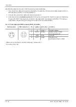
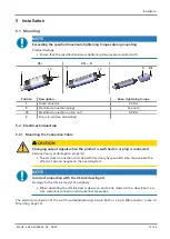
Page 13: ...onnection 5 2 1 Mounting the Connection Cable CAUTION Changing output signals when the product is switched on or plug is connected Personal injury or damage to property 4 The electrical connection mus...

Page 14: ...ach the union nut at position 10 with a maximum tightening torque of 0 8 Nm The plug must not twist or be subjected to any torque load 0 Nm If the plug is subjected to torque during mounting the torqu...

Page 15: ...ach switch a junction of several C Q cables is not possible with only one IO Link master port The IO Link master must be connected in the configuration of the automation system in the same way as othe...

Page 16: ...nal types for each signal output The setting is independent of the version The vacuum switch is factory set to PNP 7 2 Analog output Only the version VSi V SA has an analog output The integrated senso...

Page 17: ...er mirrors all setting parameters for the device in a sepa rate non volatile memory When a device is swapped for a new one of the same type the setting parame ters for the old device are automatically...

Page 18: ...d service app This per mits not only read access but also active reconfiguration of the parameters via NFC The Schmalz ControlRoom app is available at the Google Play Store The following instructions...

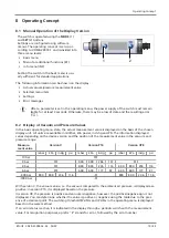
Page 19: ...e in millibar kilo pascal inch hg and PSi The information displayed varies depending on the device version and the position of the measurement value in the vacuum and pressure range Measure ment value...

Page 20: ...t range In this case the desired range for the new value is set at the start of the editing process The text Pr5 for pressure or vAC for vacuum will firstly flash and can be selected accordingly For n...

Page 21: ...r 2 seconds the system automatically returns to the 5P1 menu parameter Example of Setting the Mode Changing switching point mode 1 from x no to C no The switch is located in the Extended Functions EF...

Page 22: ...1 minute write protection is activated The entry of an invalid PIN is rejected with the message LoC 8 6 Leaving the Menu Automatically The menus automatically close if no buttons are pressed for 1 mi...

Page 23: ...on switching output 2 see Ou1 d51 Switch on delay for switching point 1 In ms this parameter is not displayed in the menu if the switching point is in condition monitoring mode C no dr1 Switch off del...

Page 24: ...erial numbers are 9 digit whole numbers These numbers are divided into 3 blocks of 3 numbers when shown on the display One of the decimal points will flash to indicate whether it is refer ring to the...

Page 25: ...ch IO Link Device Access Locks Page 32 Extended device access locks See ch Extended Device Access Locks Page 32 Menu PIN See ch PIN Code for Write Protec tion Page 31 NFC PIN Access Rights PIN Code fo...

Page 26: ...easurement range is transmitted instead of a measurement value see Special Values in the data dictionary These numbers should not then be interpreted as measurement values but as an indicator of an ov...

Page 27: ...x as a pressure switch or vacuum switch Values are considered bigger when they are further from zero and as smaller when they are closer to zero The following diagram shows the switching point behavio...

Page 28: ...to window mode the current switching points SPx and rPx are interpreted as window points FHx and FLx They are the same internal parameters also see the data dictionary If the resulting set of paramete...

Page 29: ...case the switching point is also activated when the leakage monitoring issues a warning With the V and VP8 versions diagnostics mode also includes the functionality of the condition monitoring mode at...

Page 30: ...can only be defined for the switching point SP1 In Con dition monitoring mode the parameters dSx and drx are also not shown on the display Due to the switch on and switch off delay short term fluctuat...

Page 31: ...the counter statuses and serial numbers 9 7 3 ECO Mode The product offers the option of switching off or dimming the display to save energy ECO mode can be activated and deactivated in the EF menu un...

Page 32: ...celed using IO Link not on the device itself 9 8 3 Extended Device Access Locks In the extended device access locks parameter you have the option of completely preventing NFC access or limiting it to...

Page 33: ...the switch and can be queried The maximum and minimum values can be reset via IO Link or NFC during operation using the appropri ate system commands For pressure vacuum HI LO this can also be done in...

Page 34: ...nal injury 4 Avoid possible danger zone 4 Remain vigilant All the setting parameters for the product are reset to factory settings using this function The function for resetting factory settings does...

Page 35: ...Hold the reader at the intended po sition on the product for longer No parameters can be changed using the NFC function The PIN for NFC write protection is activated via IO Link 4 Enable the NFC writ...

Page 36: ...neumatic connection before CAL is carried out E07 Under volt age US Supply voltage is too low 4 Check power supply unit and power load E08 Communica tion canceled IO Link communication canceled withou...

Page 37: ...white spirit or thin ners Only use cleaning agents with a pH between 7 and 12 2 Remove dirt on the exterior of the device with a soft cloth and soap suds at a maximum tempera ture of 60 C Make sure t...

Page 38: ...ith its corresponding operating and assembly instructions In the case of inappropriate handling or use of force any warranty and liability claims shall be void Damage and defects resulting from inadeq...

Page 39: ...Disposing of the Product 1 Dispose of the product properly after replacement or decommissioning 2 Observe the country specific guidelines and legal obligations for waste prevention and disposal 14 2 M...

Page 40: ...00 M12 4 PUR M8 4 female connector with M12 4 plug 21 04 05 00264 Connection cable VSi ASK S B M12 4 5000 M12 4 PUR M12 4 female connector with M12 4 plug 21 04 05 00265 Screw in tool MONT VORR MON VS...

Page 41: ...EN ISO 12100 Safety of machinery General principles for design Risk assessment and risk reduction EN 61000 6 1 Electromagnetic Compatibility Immunity EN 61000 6 4 A1 Electromagnetic compatibility Par...

Page 42: ...ting locked with pin code 91 0x005B 0 2 bytes 0 999 rw 0 Pass code for writing data from NFC app 73 0x0049 0 P n 1 byte 0 1 rw 0 0 PNP 1 NPN 74 0x004A 0 uni 1 byte 0 3 rw 0 0 mbar 1 kPa 2 inHg 3 psi 7...

Page 43: ...or VSi P10 Bit 5 Primary voltage US outside of optimal range 160 0x00A0 0 Actual Leakage Rate 2 bytes ro Leakage rate unit mbar sec not for VSi P10 ID 0x0000 0x0002 0x0007 0x000A 0x0017 0x000C 0x000D...

Page 44: ...J Schmalz GmbH EN US 30 30 01 00956 03 05 22 Subject to technical changes without notice...

Reviews: