Description of Functions
EN-US · 30.30.01.00956 · 03 · 05/22
33 / 44
9.9.2 User-Specific Localization
The following parameters are available for each vacuum switch when saving user-specific information:
•
Identification of the installation location
•
Identification of the storage location
•
Equipment labeling from the circuit diagram
•
Installation date
•
Geo-location
•
Web link to the relevant IODD
The parameters are ASCII character strings with the maximum length given in the data dictionary. They
can also be used for other purposes if necessary.
The NFC web link parameter is a special feature (link to IoT server). This parameter must include a valid
web address beginning with http:// or https:// and is automatically used as a web address for NFC read ac-
cess operations.
As a result, read access operations from smart phones or tablets are rerouted e.g. to an address in the
company's own intranet or a local server.
9.10 System Monitoring and Diagnostics
9.10.1 Minimum and Maximum Values
The maximum and minimum pressure/vacuum and operating voltage values that were measured since the
last switch-on are logged by the switch and can be queried.
The maximum and minimum values can be reset via IO-Link or NFC during operation using the appropri-
ate system commands.
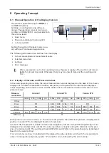
For pressure/vacuum (HI/LO), this can also be done in the operating menu under the EF menu and the
rxL
parameter.
9.10.2 Counters
The vacuum switch has two non-erasable counters
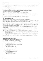
cc1
and
cc2
as well as two erasable counters
ct1
and
ct2
in the INF menu.
These counters count the positive switching ramps of the switching points 1 and 2:
Designation
Display code or param-
eter
Description
Counter 1
cc1
Counter for positive switching ramps SP1 (non-erasable)
Counter 2
cc2
Counter for positive switching ramps SP2 (non-erasable)
Counter 3
ct1
Counter for positive switching ramps SP1 (erasable)
Counter 4
ct2
Counter for positive switching ramps SP2 (erasable)
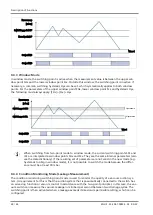
The average switching frequency of the air saving function can be determined using the difference be-
tween counters 1 and 2.
The erasable counters ct1 and ct2 can be reset to 0 during operation via IO-Link by using the appropriate
system commands.
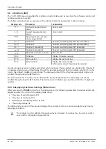
In the operating menu, this is possible via the INF menu and the parameter
rct
.
The storage of the non-erasable counter readings only occurs every 500 steps. That means that when the
operating voltage is switched off, up to 499 steps of the counter are lost.

