4
Operating instructions
Safety-monitoring module
EN
AES 2355/2356; AES 2555/2556
AES 2365/2366; AES 2565/2566
8 Appendix
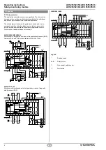
8.1 Wiring examples
The application examples shown are suggestions. They however do
not release the user from carefully checking whether the switchgear
and its set-up are suitable for the individual application.
The wiring diagram is shown with guard doors closed and in a de-
energised condition. Inductive loads (e.g. contactors, relays, etc.)
are to be provided with suitable interference suppression circuitry.
Do not connect additional loads to terminal S..
AES 2355/2356/2555/2556
Monitoring of safety guards by means of magnetic safety sensors (BNS)
Contacts 43/44 and 51/55 not available for AES 2355 / 2356
2555
2556
L1
A1
A1
100mA
S13
S1
S2
S13
K1
K3
A2
max.
Y1
Y2
X1
X7
X8
GND
PE
14
24
34
X2
K4
3
K2
S14
S14
S21
S21
S22
S22
13
24...230V AC/DC
GND
N
M
23
33
A2
24...230V AC/DC
43
44
51
52
AES 2365 / 2365
Monitoring of two independent safety guards by means of magnetic
safety sensors (BNS)
A1
A1
100mA
S13
S1
S2
S13
K1
A2
max.
Y1
Y2
X1
X7
X8
GND
PE
14
24
34
X2
K2
S14
S14
S21
S21
S22
S22
13
24...230V AC/DC
23
33
A2
24...230V AC/DC
BK
BU
BN
WH
L1
GND
S
AES 2365/2366
BK
BU
BN
WH
K3
K4
N
3
M
AES 2565 / 2566
L1
A1
A1
A2
A2
100mA
S13
S13
K1
K3
max.
Y1
Y2
X1
X2
K4
3
K2
S14
S1
S2
S14
S21
S21
S22
S22
X7
X8
GND
PE
14
24
34
13
24...230V AC/DC
24...230V AC/DC
GND
N
M
23
33
43
44
51
52
AES 2565/2566
Legend
A
Positive break
A - D
Safety switch
S
Non-contact safety sensor
H
Start button


