5
EN
AES 2355/2356; AES 2555/2556
AES 2365/2366; AES 2565/2566
Operating instructions
Safety-monitoring module
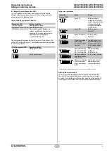
8.2 Integral System Diagnostics (ISD)
The LED indication of the safety-monitoring modules shows the
different switching conditions and errors.The switching conditions
are explained in the following tables.
Tables switching condition indication
Diagnostic LED
System condition
The LED is green.
Enabling paths closed
LED lashes yellow (0.5 Hz)
Enabling paths open
LED lashes yellow (2 Hz)
Safety guard closed, however no
release; possible causes: incorrect
operation (only one contact actuated
upon opening) or voltage drop
→ perform start-up test
The safety-monitoring modules have two more LED indications. The
yellow LED is intermittently on. The switching conditions are explained
in the following tables.
Indication (yellow) LED
System condition
1 impulse
Safety guard 1 open
2 impulses
Safety guard 2 open
Table error indications
Indication
(orange) LED
Error
Cause
1 impulse
Inputs S1
Defective supply
voltage lead, defective
switch, erroneous itting
of the switch; switch
only partially actuated
for at least 5 s
2 impulses
Inputs S2
Refer to errors
inputs S1
3 impulses
Inputs S1 and S2
Refer to errors
inputs S1
4 impulses
Interference signals
at the inputs
(no safe evaluation
assured)
Too high capacitive or
inductive interference
at the switch's cables
or the supply voltage
lead
5 impulses
One or both relays
did not close within
the monitoring time
Too low operating
voltage U
e;
Defective relay
6 impulses
Relay not disabled
upon the actuation
of the switch
Relay contact welding
7 impulses
Dynamic monitoring
of both channels
(cross-monitoring)
failure
Fault in one channel;
internal data trans-
mission interrupted
* Partial actuation: position of the switch, in which only one contact was actuated.
Deleting the error message
The error message is deleted, when the error cause is eliminated
and the AES can check all functions. In case of an error of switch 1
or switch 2, actuate the switch concerned (open the safety guard and
close it again). For all other errors, both switches must be actuated.


