3
AES 9107
Operating instructions
Safety-monitoring module
EN
The application examples shown are suggestions They however do not
release the user from carefully checking whether the switchgear and
its set-up are suitable for the individual application The wiring diagram
is shown with guard doors closed and in a de-energised condition
Inductive loads (eg contactors, relays, etc) are to be provided with
suitable interference suppression circuitry
As far as the electrical safety is concerned, the protection
against unintentional contact of the connected and therefore
electrically interconnected apparatus and the insulation of the
feed cables must be designed for the highest voltage, which
can occur in the device
To avoid EMC disturbances, the physical ambient and
operational conditions at the place where the product
is installed, must meet the provisions laid down in the
paragraph "Electromagnetic Compatibility (EMC)" of
IEC 60204-1
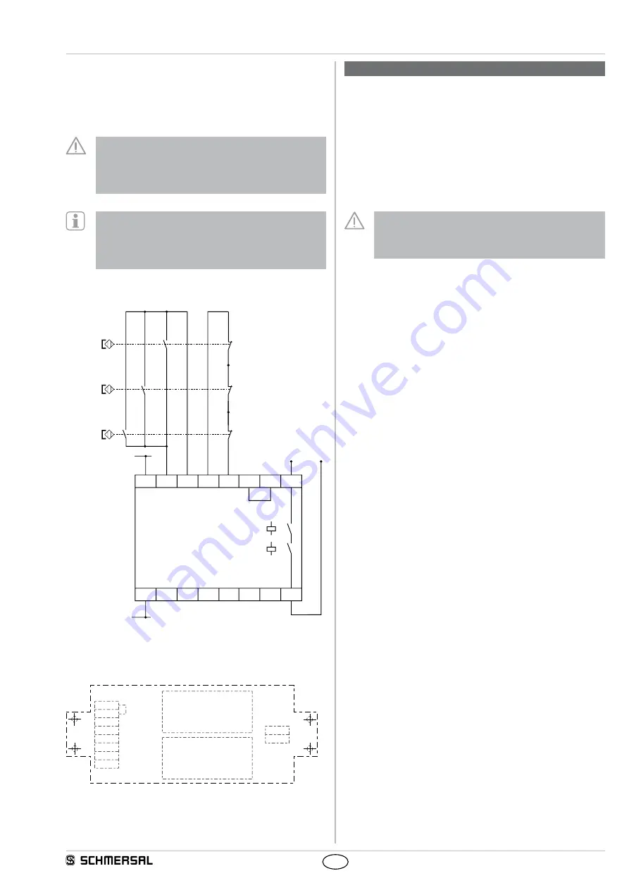
4.2 Wiring example
K1
K2
A1
14
A2
S22
X1
X2
S14
S13
S21
13
+ 24 VDC
AES 9107
0 V
BK
BU
WH
BN
BN
BN
WH
WH
BK
BK
BU
BU
BU
WH
BNS 260-11z
BNS 260-11z
BNS 260-11z
4.3 Printed circuit board top view
Terminals X1 and X2 without function
K1
X1
X2
S13
S14
S21
S22
A2
A1
14
13
K2
5. Operating principle and settings
5.1 Operating principle after the operating voltage is switched on
The safety-monitoring module checks whether the enabling contacts of
the relay are opened If the safety guard is closed, the enabling path of
the safety-monitoring module is closed The cables and the connected
safety switches are tested when the safety guards are opened This
check expects a signal change on both inputs of the switch when the
safety guard is opened If this change does not take place, the release
is blocked, even when the "right" signals for this situation are measured
at the inputs when the safety guard is closed again When the safety
guard is opened, the enabling path of the safety-monitoring module is
opened as well
The circuit of the output current by the approach of
the magnetic switch must only be closed, when the
mechanical interlock installed to the door is engaged into
its bearing at least 7 mm
Inputs
A1, A2: Supply voltage 24 VDC
S13/S14: Terminals of the NO contact of the
safety switch S13 = input, S14 = GND
S21/S22: Terminals of the NC contact of the
safety switch S21 = input, S22 = GND
Output
13, 14: Normally-open contact for safety functions
Functional testing
1 Switch the supply voltage on
2 Open the hook bar (magnetic switch actuated)
3 The safety circuit (terminals 13/14) must be opened
4 Close the hook bar (magnetic switch not actuated)
5 The safety circuit must be closed
5.2 Check of the error detection
Detection "NC contact does not open"
1 Switch the supply voltage on
2 Close the hook bar (magnetic switch not actuated)
3 The safety circuit (terminals 13/14) must be closed
4 Bypass terminals S13-S14 (simulates closing)
5 The safety circuit (terminals 13/14) must be opened
6 Remove the bridge
7 The safety circuit (terminals 13/14) must remain open
8 Switch the voltage of the device off for 1 second, then switch the
voltage back on The initial condition is restored
Detection "NO contact does not close"
1 Switch the supply voltage on
2 Close the hook bar (magnetic switch not actuated)
3 The safety circuit (terminals 13/14) must be closed
4 Disconnect terminal S22 (simulates opening)
5 The safety circuit (terminals 13/14) must be opened
6 Reconnect terminal S22
7 The safety circuit (terminals 13/14) must remain open
8 Switch the voltage of the device off for 1 second, then switch the
voltage back on The initial condition is restored


