4
Operating instructions
Solenoid interlock
AZM 161 AS
EN
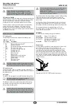
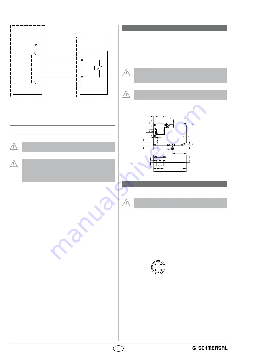
AUX +
AUX -
+24 VDC
0 VDC
PL ?
PFH
D
?
Safety power
shutdown
Solenoid
interlock
Guard locking
function
To simplify classification of the release function, the following
parameters can be assumed for the device:
PL:
e
Control Category:
4
PFH:
≤ 1.00 x 10
-9
/ h
SIL:
suitable for SIL 3 applications
Mission time:
20 years
Fault exclusion with regard to wiring routing
must be observed.
If for a certain application the power to unlock version of
a solenoid interlock cannot be used, for this exception
an interlock with power to lock can be used if additional
safety measure need to be realised that have an
equivalent safety level.
3. Mounting
3.1 General mounting instructions
Three mounting holes are provided for fixing the enclosure. The
solenoid interlock is double insulated. The use of an earth wire is not
authorised. The solenoid interlock must not be used as an end stop.
Any mounting position. The mounting position however must be chosen
so that the ingress of dirt and soiling in the used opening is avoided.
Unused actuator openings must be sealed with slot sealing plugs.
The safety component and the actuator must be permanently fit-
ted to the safety guards and protected against displacement by
suitable measures (tamperproof screws, gluing, drilling, pinning).
Please observe the remarks of the standards ISO 12100,
ISO 14119 and ISO 14120.
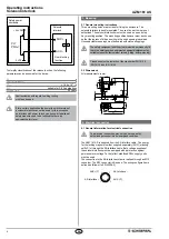
3.2 Dimensions
All measurements in mm.
90
56
M12
5,5
7
18
6
6
6
6
8
29
40
72
16,5
15,8
30
130
104
28
8
26
4. Electrical connection
4.1 General information for electrical connection
The electrical connection may only be carried out by
authorised personnel in a de-energised condition.
The AZM 161 AS is supplied from the AS-Interface cable. The energy
for the locking magnets is either supplied separately (AUX) (ordering
suffix P) or through the AS-Interface cable. Both voltage supplies of
the solenoid interlock must be equipped with a protection against
permanent overvoltage. To that effect, stabilised PELV supply units
must be used.
The connection to the AS-Interface system is realised through an M12
connector. The M12 connector is A-coded. The wiring configuration is
defined as follows (to EN 62026-2):
AUX +(P)
3
2
1
4
AS-Interface -
AS-Int
AUX -(P)

