5
AZM 170 I
Operating instructions
Solenoid interlock
EN
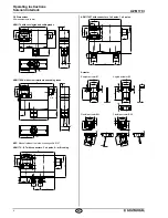
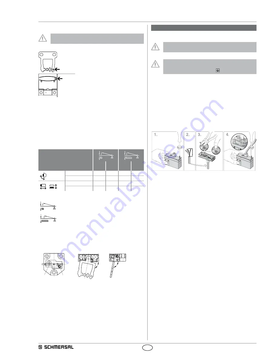
Mounting of the actuator
The marks on the used actuator opening of the solenoid
interlock and on the actuator must be opposite.
Please observe that, when fixing the switch e.g. by means of rivetting
or welding, the insertion depth of the actuator is not modified. Different
actuator forms are available. The actuators B1 and B5 are preferably
used for sliding and removable safety guards. For hinged guards, the
B6R and B6L actuators.
When the switch is fitted on a hinged safety guard, please ensure that
the point of rotation is located within the range of the upper surface of
the safety switch, in which the actuator hook is inserted (refer to table).
Actuating radii
d
R min.
d
R min.
R
min
[mm]
d
[mm]
R
min
[mm]
d
[mm]
B6L
50
11
50
11
B6R
50
11
50
11
B1
–
–
–
–
B5
–
–
–
–
Key
d
d
R min.
R min.
Actuating radius over the small edge of the actuator
d
d
R min.
R min.
Actuating radius over the wide edge of the actuator
The axis of the hinge must be d mm above and in a parallel plane to the
top surface of the safety switch. The basis setting provides a minimum
radius of Rmin.
Actuator B6L / B6R
b
a
a
b
b
a
a
b
b
a
a
b
The B6L or B6R actuators are set to the smallest radius in factory. To
increase the radius, the setting screws a + b must be turned by means
of a hexagonal key A/F 2.5 mm.
4. Electrical connection
4.1 General information for electrical connection
The electrical connection may only be carried out by
authorised personnel in a de-energised condition.
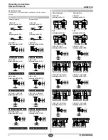
If the risk analysis indicates the use of a monitored interlock
they are to be connected in the safety circuit with the
contacts indicated with the symbol .
For the cable entry, suitable cable glands with an appropriate degree of
protection must be used.
Cut clamp terminals
The IDC method of termination (cut clamp technology) enables
connecting flexible wires with cable section 0.75 - 1 mm
2
without using
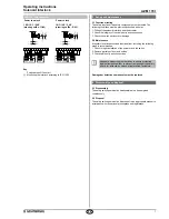
conductor ferrules. To this effect, strip the wire according to the drawing
(refer to the wiring example) and insert it into the cable gland, close the
cable gland, push the conductors in the groove of the cover (refer to
wiring example) and screw the cover back. Observe that the individual
conductors remain in position to avoid jamming.
70
mm
Screw terminals (SK version)
Unscrew the cover of the enclosure. Connect the cables to the terminal
block. Use insulated conductor ferrules to that effect. Screw the cover
back on the enclosure.

