7
AZM 170 I
Operating instructions
Solenoid interlock
EN
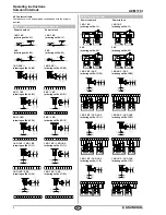
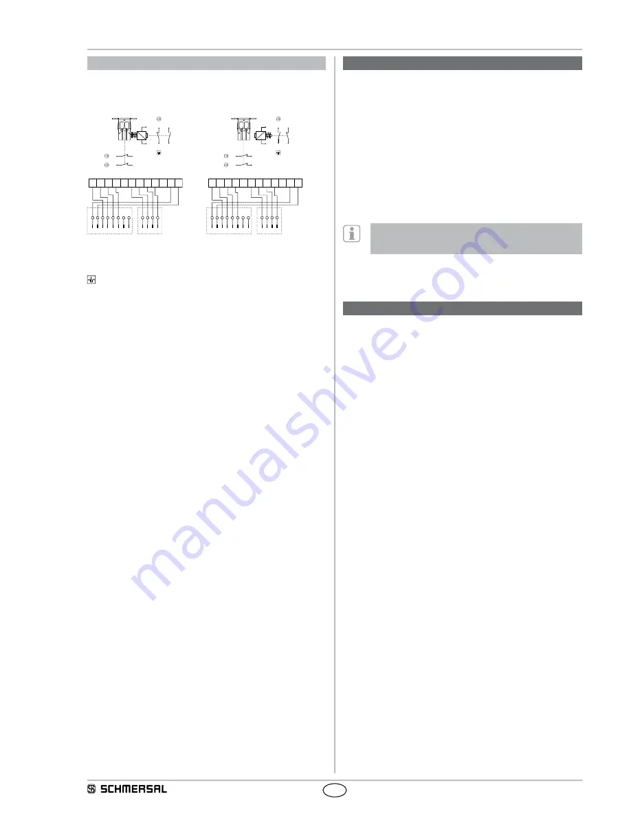
AZM 170 I with connector
Power to unlock
Power to lock
1 NO 1 NC / 2 NC
(ordering suffix -11/02)
1 NO 1 NC / 2 NC
(ordering suffix -11/02)
11
13
14
12
A1
41
31
32
42
A2
31
41 42
32
A1 A2
1 2 3 4
13
11 12
14
1 2 3 4 5 6 7 8
31
41 42
32
A1 A2
1 2 3 4
13
11 12
14
1 2 3 4 5 6 7 8
A1
11
13
14
12
41
31
32
42
A2
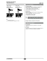
Key
A
Positive break NC contact
Monitoring the interlock according to ISO 14119
5. Set-up and maintenance
5.1 Functional testing
The safety function of the safety components must be tested. The
following conditions must be previously checked and met:
1. Fitting of the solenoid interlock and the actuator
2. Check the integrity of the cable entry and connections
3. Check the switch enclosure for damage
5.2 Maintenance
A regular visual inspection and functional test, including the following
steps, is recommended:
1. Check for tight installation of the actuator and the switch
2. Remove particles of dust and soiling
3. Check cable entry and connections
Adequate measures must be taken to ensure protection
against tampering either to prevent tampering of the safety
guard, for instance by means of replacement actuators.
Damaged or defective components must be replaced.
6. Disassembly and disposal
6.1 Disassembly
The safety switchgear must be disassembled in a de-energised
condition only.
6.2 Disposal
The safety switchgear must be disposed of in an appropriate manner in
accordance with the national prescriptions and legislations.

