background image

16

Operating instructions

Solenoid interlock

AZM201

EN

2.6  Safety classification

- of the interlocking function 

Standards: 


ISO 13849-1, IEC 61508, IEC 62061

PL: 

 e 

Control Category:

 4

PFH:


1.9 x 10

-9

 / h

PFD:


1.6 x 10

-4

SIL:


suitable for SIL 3 applications

Mission time:


20 years

- of the guard locking function 

Standards: 


ISO 13849-1, IEC 61508, IEC 62061

PL: 

 d

Control Category:

 2

PFH:


1.0 x 10

-8

 / h  

PFD:


8.9 x 10

-4

SIL:


suitable for SIL 2 applications

Mission time:


20 years

The safety consideration of the guard locking function 

only applies for standard devices with monitored solenoid 

interlock AZM201Z-…-1P2PW-… (see Ordering code). 

A safety assessment of the guard locking function for 

devices with serial diagnostics "SD2P" is not allowed due to 

the non-safe locking/unlocking signal from the SD Gateway

The actuation of the interlock must be compared with the 

external OSSD enabler. If a shut-down now occurs due to 

an unintentional unlocking this is detected by an external 

diagnostic.

If for a certain application the power to unlock version of a 

solenoid interlock cannot be used, then for this exception an 

interlock with power to lock can be used if additional safety 

measure need to be realised that have an equivalent safety 

level.

The safety analysis of the guard locking function refers to the 

component solenoid interlock AZM as part of the complete 

system.

On the customer side further measures such as safe 

actuation and safe cable installation to prevent faults are to 

be implemented.

In the event of a fault resulting in the unlocking of the guard 

locking, this is detected by the solenoid interlock and the 

safety gates Y1/Y2 switch off.  When such a fault occurs 

the protection equipment may open immediately, just once, 

before the safe condition of the machine is reached.  The 

system reaction of category 2 allows that a fault can occur 

between tests causing the loss of the safety function which is 

detected by the test.

3.  Mounting

3.1  General mounting instructions

Please observe the relevant requirements of the 

standards ISO 12100, ISO 14119 and ISO 14120.

For fitting the solenoid interlock, two mounting holes for M6 screws 

with washers (washers included in delivery) are provided. The solenoid 

interlock must not be used as an end stop. Any mounting position. 

The mounting position however must be chosen so that the ingress of 

dirt and soiling in the used opening is avoided. The unused actuator 

opening must be sealed by means of the dust-proof flap (included in 

delivery). 

Minimum distance between two solenoid interlocks  

as well as other systems with same frequency (125 kHz): 100 mm.

Mounting of the solenoid interlock and the actuator

Refer to the mounting instructions manual for the corresponding 

actuator.

The actuator must be permanently fitted to the safety guards 

and protected against displacement by suitable measures 

(tamperproof screws, gluing, drilling of the screw heads). 

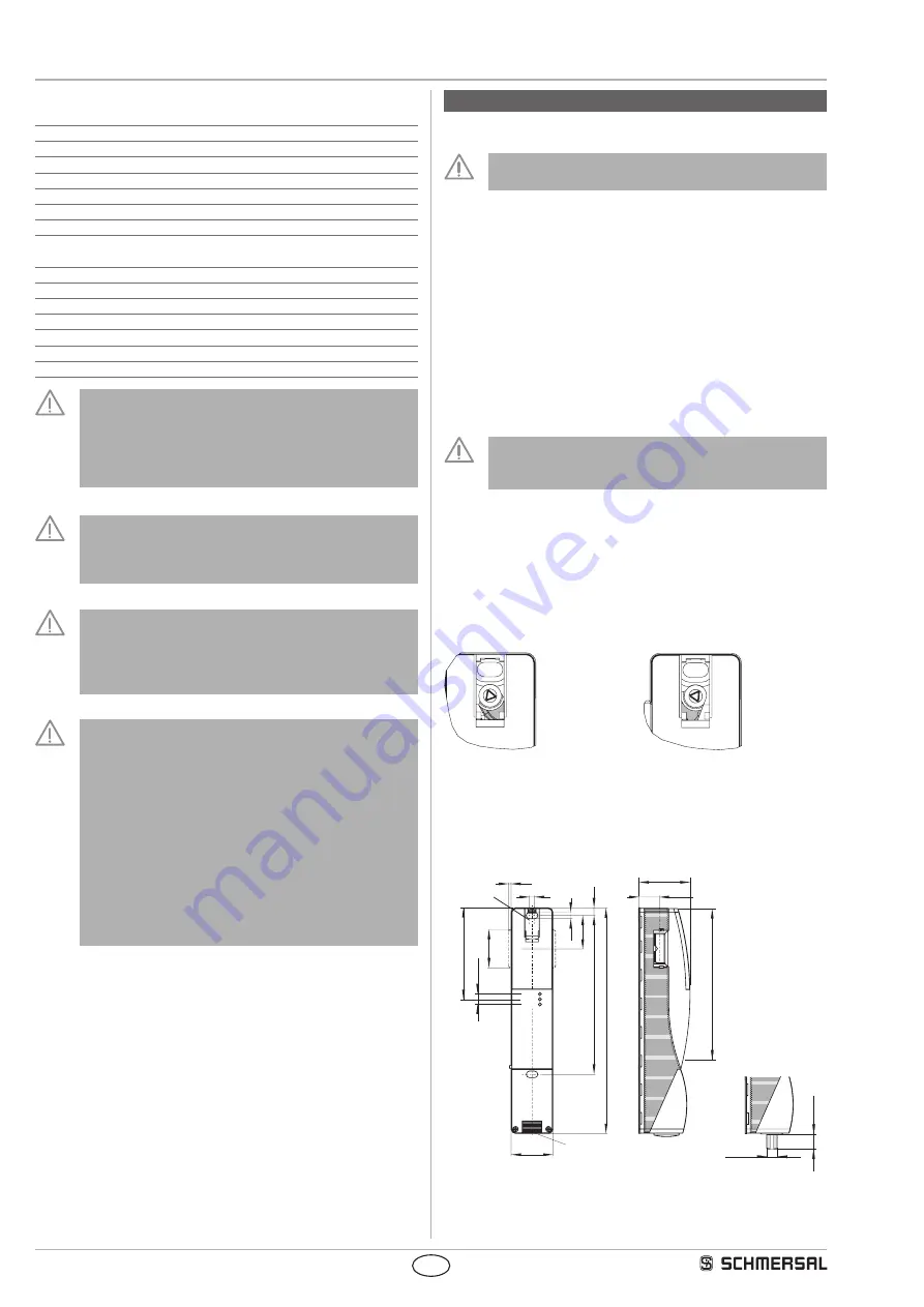
3.2  Manual release

For the machine set-up, the solenoid interlock can be unlocked in a de-

energised condition. After opening of the plastic flap "A" (refer to image 

"Dimensions"), the triangular key must be turned clockwise to bring the 

blocking bolt in unlocking condition. The normal locking function is only 

restored after the triangular key has been returned to its original position. 

Caution: do not turn beyond the latching point! After being put into 

operation, the manual release must be secured by closing the plastic flap 

"A" and affixing the seal, which is included in delivery.

Component ready  

for operation

Component not ready  

for operation

3.3  Dimensions

All measurements in mm.

40

220

155,5

5

6,5

32,5

38

7,5

M20x1,5

3,3

20 1

±

50

M12

Power

Fault

Status

150


(B)

15,5

13,3

89

A

Key

A: Manual release

B: Active RFID area

Summary of Contents for AZM201

Page 1: ...1 2 Zielgruppe autorisiertes Fachpersonal 1 1 3 Verwendete Symbolik 1 1 4 Bestimmungsgemäßer Gebrauch 1 1 5 Allgemeine Sicherheitshinweise 1 1 6 Warnung vor Fehlgebrauch 2 1 7 Haftungsausschluss 2 2 Produktbeschreibung 2 1 Typschlüssel 2 2 2 Sonderausführungen 2 2 3 Umfassende Qualitätssicherung gemäß 2006 42 EG 2 2 4 Bestimmung und Gebrauch 2 2 5 Technische Daten 3 2 6 Sicherheitsbetrachtung 4 3 ...

Page 2: ... führt Schmersal in Eigenverant wortung auch die CE Kennzeichnung von in Anhang IV gelisteten Produkten durch Darüber hinaus senden wir Ihnen Baumusterprüf bescheinigungen auf Wunsch zu oder sie können im Internet unter www schmersal com abgerufen werden 2 4 Bestimmung und Gebrauch Das berührungslos wirkende elektronische Sicherheitsschaltgerät ist für den Einsatz in Sicherheitsstromkreisen ausgel...

Page 3: ...e C1 C2 C3 Elektrische Daten Sicherheitsausgänge Sicherheitsausgänge Y1 und Y2 Ausführung der Schaltelemente OSSD p schaltend kurzschlussfest Gebrauchskategorie DC 13 Ue Ie 24 VDC 0 25 A Bemessungsbetriebsstrom le je max 0 25 A Reststrom Ir 0 5 mA Spannungsfall Ud 4 V Querschlussüberwachung durch Gerät ja Testimpulsdauer 0 5 ms Testimpulsintervall 1 000 ms Klassifizierung ZVEI CB24I Quelle C2 Senk...

Page 4: ...er sichere Zustand der Maschine erreicht ist Das Systemverhalten der Kategorie 2 lässt zu dass zwischen den Tests das Auftreten eines Fehlers zum Verlust der Sicher heitsfunktion führen kann und der Verlust der Sicherheits funktion durch den Test erkannt wird 3 Montage 3 1 Allgemeine Montagehinweise Bitte beachten Sie die Hinweise der Normen ISO 12100 ISO 14119 und ISO 14120 Zur Befestigung der Si...

Page 5: ...nd Reihenschaltung von SD Geräten stehen die SD Verteiler PFB SD 4M12 SD Variante für die Feldebene und PDM SD 4CC SD Variante für den Schaltschrank aufschiebbar auf Tragschiene sowie weiteres umfangreiches Zubehör zur Verfügung Detailinfo im Internet unter products schmersal com Im Lieferumfang von 1P2PW und SD2P enthalten ist die montierte Brücke 24V X1 X2 4 2 Leitung Die Leitungseinführung erfo...

Page 6: ...otential Quer schluss führt zur verzögerten Abschaltung siehe Tabelle 2 Nach der Behebung des Fehlers wird die Fehlermeldung durch das Öffnen der zugehörigen Schutztür und erneutes Sperren quittiert Die Sicherheitsausgänge schalten ein und geben die Anlage erneut frei Eine Zuhaltungskette muss zum erneuten Einschalten durchgehend gesperrt sein Eine automatische elektronische Verriegelung erfolgt w...

Page 7: ...lernen gestartet aus an blinkt 0 V 0 V 0 V Nur I2 Betätiger Anlernvorgang Freigabesperre blinkt aus aus 0 V 0 V 0 V 1 nach 30 min Abschaltung wegen Fehler 2 s Blinkcode Tabelle 2 Fehlermeldungen Blinkcodes rote Diagnose LED Blinkcodes rot Bezeichnung eigenständige Abschaltung nach Fehlerursache 1 Blinkpuls Fehler warnung an Ausgang Y1 30 min Fehler im Ausgangstest oder Spannung am Ausgang Y1 obwoh...

Page 8: ...eitung wird entweder das PROFIBUS Gateway SD I DP V0 2 oder das Universal Gateway SD I U eingesetzt Dieses serielle Diagnose Interface wird als Slave in ein vorhandenes Feldbus System eingebunden Die Diagnosesignale können auf diese Weise mit einer SPS ausgewertet werden Die notwendige Software zur Einbindung der SD Gateways steht im Internet unter products schmersal com zur Verfügung Die Antwortd...

Page 9: ... Sitz prüfen 2 Maximalen seitlichen Versatz von Betätigereinheit und Sicherheits schalter prüfen 3 Entfernen von Schmutzresten 4 Prüfen der Leitungseinführung und anschlüsse In allen betriebsmäßigen Lebensphasen des Sicherheits schaltgerätes sind konstruktiv und organisatorisch geeignete Maßnahmen zum Manipulationsschutz beziehungsweise ge gen das Umgehen der Sicherheitseinrichtung beispielsweise ...

Page 10: ...änge eingespeist Die Sicherheitsausgänge des ersten Sicherheitsschaltgerätes werden auf die Auswertung geführt X1 Y1 X2 Y2 1 2 3 5 6 8 X1 X2 24V GND Y1 Y2 1 2 3 5 6 8 X1 4 Y1 4 Y1 X2 7 Y2 7 Y2 OUT 24V GND OUT SPS PLC IN SPS PLC SPS PLC IN 24 VDC GND SPS PLC Sicherheitsausgänge Auswertung Anschlussbeispiel 2 Reihenschaltung AZM201 mit serieller Diagnosefunktion Die Sicherheitsausgänge des ersten Si...

Page 11: ...sgang SD Ausgang 5 9 GY GY X2 Sicherheitseingang 2 6 3 PK PK Y2 Sicherheitsausgang 2 7 8 BU VT IN Magnetansteuerung SD Eingang 8 4 RD OR ohne Funktion 6 Ansicht Klemmleisten für Bestellindex SK bzw CC Ansicht Ausführung mit abnehmbaren Klemmleisten Y1 Y2 OUT GND 24V 24V X1 X2 IN AZM 200 1P2P AZM201 1P2PW Y1 Y2 OUT GND 24V 24V X1 X2 IN AZM 200 SD2P AZM201 SD2P 7 8 9 5 1 2 3 4 6 AZM 200 1P2P AZM201 ...

Page 12: ...ür Sicherheitsfunktionen Einschlägige Richtlinien Maschinenrichtlinie RED Richtlinie RoHS Richtlinie 2006 42 EG 2014 53 EU 2011 65 EU Angewandte Normen EN 60947 5 3 2013 ISO 14119 2013 EN 300 330 V2 1 1 2017 EN ISO 13849 1 2015 EN 61508 Teile 1 7 2010 EN 62061 2005 AC 2010 A1 2013 A2 2015 Benannte Stelle der Baumusterprüfung TÜV Rheinland Industrie Service GmbH Alboinstr 56 12103 Berlin Kenn Nr 00...

Page 13: ... the Internet products schmersal com Content 1 About this document 1 1 Function 13 1 2 Target group authorised qualified personnel 13 1 3 Explanation of the symbols used 13 1 4 Appropriate use 13 1 5 General safety instructions 13 1 6 Warning about misuse 14 1 7 Exclusion of liability 14 2 Product description 2 1 Ordering code 14 2 2 Special versions 14 2 3 Comprehensive quality insurance to 2006 ...

Page 14: ...rehensive quality insurance to 2006 42 EC Schmersal is a certified company to appendix X of the Machinery Directive As a result Schmersal is entitled to autonomously conduct the conformity assessment procedure for the products listed in Appendix IV of the MD without involving a notified body The prototype test certificates are available upon request or can be downloaded from the Internet at www sc...

Page 15: ...1 Source C1 C2 C3 Electrical data Safety outputs Safety outputs Y1 and Y2 Switching elements OSSD p type short circuit proof Utilisation category DC 13 Ue Ie 24 VDC 0 25 A Rated operating current Ie each max 0 25 A Leakage current Ir 0 5 mA Voltage drop Ud 4 V Cross wire monitoring by device Yes Test pulse duration 0 5 ms Test pulse interval 1 000 ms Classification ZVEI CB24I Source C2 Sink C1 C2 ...

Page 16: ...he machine is reached The system reaction of category 2 allows that a fault can occur between tests causing the loss of the safety function which is detected by the test 3 Mounting 3 1 General mounting instructions Please observe the relevant requirements of the standards ISO 12100 ISO 14119 and ISO 14120 For fitting the solenoid interlock two mounting holes for M6 screws with washers washers incl...

Page 17: ...le on the Internet products schmersal com The fitted 24V X1 X2 bridge is included in the delivery of 1P2PW and SD2P 4 2 Cable The cable entry is realised by a metric M20 gland This gland must be measured by the user so that it is suitable for the cable used A cable gland with strain relief and suitable IP protection class must be used Settle length x of the cable at terminals of type s r or f Cage...

Page 18: ...le the reactivation Automatic electronic locking takes place if more than one fault is detected at the safety outputs or a cross circuit is detected between Y1 and Y2 This means that normal fault acknowledgement is no longer possible To reset this type of interlocking the solenoid interlock must be isolated from the power supply after elimination of the error causes Error warning A fault has occur...

Page 19: ...tor started Off On Flashes 0 V 0 V 0 V Only I2 teach in procedure actuator release block Flashes Off Off 0 V 0 V 0 V 1 after 30 min disabling due to fault 2 refer to flash code Table 2 Error messages flash codes red diagnostic LED Flash codes red Designation Autonomous switch off after Error cause 1 flash pulse Error warning at output Y1 30 min Fault in output test or voltage at output Y1 although...

Page 20: ...y SD I DP V0 2 or the Universal Gateway SD I U are used This serial diagnostic interface is integrated as a slave in an existing field bus system In this way the diagnostic signals can be evaluated by means of a PLC The necessary software for the integration of the SD Gateway is available for download at products schmersal com The response data and the diagnostic data are automatically and permane...

Page 21: ...s 1 Check for tight installation of the actuator and the switch 2 Check maximum axial offset of actuator unit and safety switch 3 Remove particles of dust and soiling 4 Check cable entry and connections Adequate measures must be taken to ensure protection against tampering either to prevent tampering of the safety guard for instance by means of replacement actuators Damaged or defective components...

Page 22: ... monitoring module The safety outputs of the first safety component are wired to the safety monitoring module X1 Y1 X2 Y2 1 2 3 5 6 8 X1 X2 24V GND Y1 Y2 1 2 3 5 6 8 X1 4 Y1 4 Y1 X2 7 Y2 7 Y2 OUT 24V GND OUT SPS PLC IN SPS PLC SPS PLC IN 24 VDC GND SPS PLC Safety outputs evaluation Wiring example 2 Series wiring of the AZM201 with serial diagnostic function The safety outputs of the first safety c...

Page 23: ...nostic output SD output 5 9 GY GY X2 Safety input 2 6 3 PK PK Y2 Safety output 2 7 8 BU VT IN Solenoid control SD input 8 4 RD OR without function 6 View of the terminal block for ordering suffix SK or CC View of the version with removable terminal blocks Y1 Y2 OUT GND 24V 24V X1 X2 IN AZM 200 1P2P AZM201 1P2PW Y1 Y2 OUT GND 24V 24V X1 X2 IN AZM 200 SD2P AZM201 SD2P 7 8 9 5 1 2 3 4 6 AZM 200 1P2P ...

Page 24: ...or safety functions Relevant Directives Machinery Directive RED Directive RoHS Directive 2006 42 EC 2014 53 EU 2011 65 EU Applied standards EN 60947 5 3 2013 ISO 14119 2013 EN 300 330 V2 1 1 2017 EN ISO 13849 1 2015 EN 61508 parts 1 7 2010 EN 62061 2005 AC 2010 A1 2013 A2 2015 Notified body for the prototype test TÜV Rheinland Industrie Service GmbH Alboinstr 56 12103 Berlin ID n 0035 EC prototype...

Reviews: