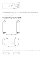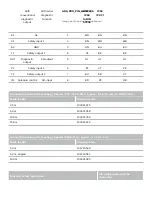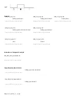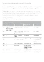
Y1 and Y2 = Safety outputs → Safety monitoring module
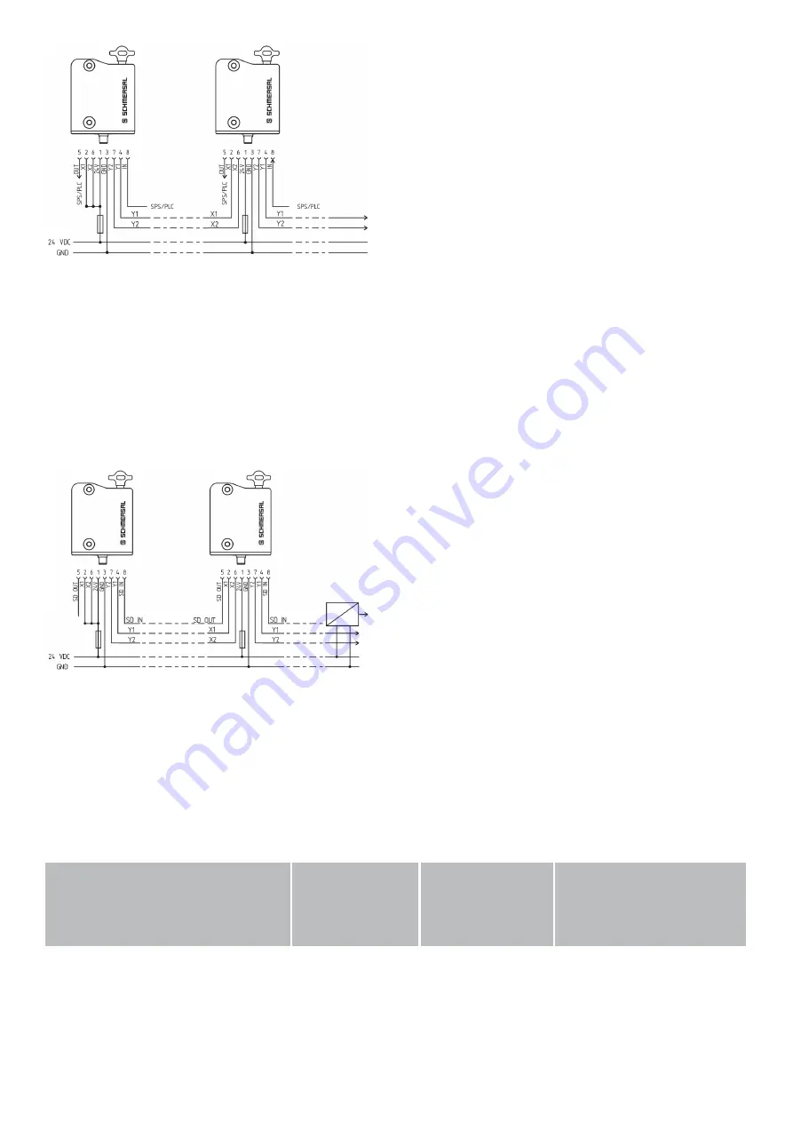
Wiring example 2: Series-wiring of the AZM300 with serial diagnostic function (max. 31 components in
series)
In devices with the serial diagnostics function (ordering suffix -SD), the serial diagnostics connections are wired in
series and connected to a SD-Gateway for evaluation purposes. The safety outputs of the first safety component are
wired to the safety-monitoring module. The serial Diagnostic Gateway is connected to the serial diagnostic input of
the first safety component.
Y1 and Y2 = Safety outputs → Safety monitoring module
SD-IN → Gateway → Field bus
4.4 Wiring configuration and connector accessories
Function safety switchgear
Pin
configuration of
the connector
Colour codes of
the Schmersal
connectors
Poss. colour code of other
commercially available
connectors according to
EN 60947-5-2

