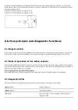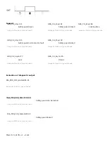
In order to enable trouble-free functionality of the device, the rotary handle must be in position I or II when the
safety guard is open. In the intermediate positions, locking is impossible. The latching force is changed by turning
the rotary handle by 180°.
In position I,the latching force is approx. 25 N.
In position II, the latching force is approx. 50 N.
6 Active principle and diagnostic functions
6.1 Magnet control
In the power to unlock version of the AZM300, the solenoid interlock is unlocked when the IN signal (= 24V) is set.
In the power to lock version of the AZM300, the solenoid interlock is locked when the IN signal (= 24 V) is set.
6.2 Mode of operation of the safety outputs
In the standard AZM300Z variant, the unlocking of the solenoid interlock causes the safety outputs to be disabled.
The unlocked safety guard can be relocked as long as the actuator is inserted in the AZM300Z solenoid interlock; in
that case, the safety outputs are re-enabled.
It is not necessary to open the safety guard.
In the AZM300B version, only the opening of the safety guard causes the safety outputs to be disabled.
6.3 Diagnostic-LEDs
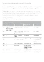
The solenoid interlock signals the operating condition, as well as errors through 3-colour LEDs.
green
(Power)
Supply voltage on
yellow
(Status)
Operating condition
red
(Fault)
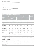
Error (see table 2: Error messages / flash codes red
diagnostic LED)


