background image

3

Anwendung/

Application

Die einzelnen Sicherheitsbausteine zum Einsatz in Sicherheitsstromkreisen sind für
den Einbau in Schaltschränken vorgesehen.

Sie dienen zur sicheren Auswertung eines Signals von zwangsöffnenden Türsicher-
heitsschaltern, Not-Aus-Schaltern, Zweihandbedienpulten, Sicherheitsschaltmatten
und -leisten (nur AZR31R2).

The safety relays are intended for use in safety interlock applications and are
designed for installation in switchgear cabinets.

They provide the positive evaluation of a signal from door mounted safety switches
with positive break, emergency stop switches, two-hand operation panels, safety mats
and safety edges (AZR31R2 only).

Aufbau/

Design

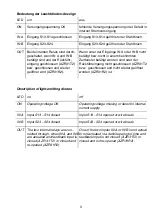
Die Sicherheitsbausteine sind zweikanalig aufgebaut. Sie enthalten zwei Sicherheits-
relais mit überwachten zwangsgeführten Kontakten. Die in Reihe geschalteten Relais
bilden den Freigabepfad. Vier grüne LEDs zeigen die Betriebszustände an.

ON:

Betriebsspannung

InA:

Kanal A

InB:

Kanal B

OUT: Freigabe

The safety relays are of a dual-channel design.They incorporate two relays with
monitored, positive guided contacts. The NO contacts of the relays, wired in series,
form the authorized operation (relay output). Four green LEDs show operational
conditions of the device.

ON:

Operating voltage

InA:

Channel A

InB:

Channel B

OUT: Authorized operation

Eingänge/

Inputs

Sicherheitsschalter mit zwei Öffnerkontakten oder einem Öffner- und einem Schlie-
ßerkontakt an den Eingängen S13-S14 und S23-S24 anschließen. Auslösekontakt an
den Eingängen X2-X3 (24 V für Reset bei AZR31R2) oder X1-X2 (Schließer für
Rückführung/Test bei AZR31T2) anschließen.

Connect the safety switch having two NC contacts or one NC contact and one NO
contact to the inputs S13-S14 and S24-S23. Connect release contact to the inputs
X2-X3 (24 V for reset with AZR 31R2) or X1-X2 (the NO contact for the feedback
control circuit/test with AZR 31T2).

Ausgänge/

Outputs

Der Sicherheitsbaustein besitzt drei Freigabepfade (Öffner) und einen Signalpfad
(Schließer).
The safety relay has three authorized operations (NC) and one signal path (NO).

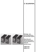
Summary of Contents for AZR31R2

Page 1: ...1 Montage und Anschlu anleitung Sicherheitsbausteine Mounting and Wiring Instructions Interlock Monitoring Modules Safety relays AZR31R2 AZR31T2 steute...

Page 2: ...A1 13 33 23 41 14 24 34 42 K2 K1 K2 X2 X3 S24 S23 RESET SUPERVISION CIRC S14 S13 13 14 K2 K1 K2 X1 X2 23 33 41 42 34 24 K1 S24 S23 PROT CIRC A2 A1 AZR31R2 33 D X3 LR17298 50 X2 S14 A2 S23 C E57648 S13...

Page 3: ...pannung InA Kanal A InB Kanal B OUT Freigabe The safety relays are of a dual channel design They incorporate two relays with monitored positive guided contacts The NO contacts of the relays wired in s...

Page 4: ...d interrupt the authorized operation To switch on again the two inputs have to be opened or the operating voltage has to be shut off The reset releases the relay again AZR31T2 1 Der Sicherheitsbaustei...

Page 5: ...eht sein positives Spannungspotential von S13 ber einen Taster an X2 und sein GND Potential von S23 an X3 Zum Ein schalten mu der Reset Eingang bet tigt werden Der Eingang reagiert nur auf einen Wechs...

Page 6: ...ed If this is bridged an automatic start up is possible The test input can be used to monitor secondary relays 2 1 Zweihandbedienpult AZR31R2 Two hand operation panels AZR31R2 Die Eing nge werden mit...

Page 7: ...rom 24 V to 0 V No automatic start up is possible The test contact can be used to monitor secondary relays 3 2 Schutzt r mit R ckf hrung AZR31T2 Safety door with control circuit AZR31T2 Die Eing nge S...

Page 8: ...dback input can be used to monitor the secondary relays 4 2 Sicherheits Schaltmatte oder Schaltleiste mit R ckf hrung AZR31T2 Safety mat or safety edge with control cicuit Hierbei wird die Verbindung...

Page 9: ...mmten Zeitfenster bet tigt worden sind oder der R ckf hreingang nicht geschlossen AZR31T2 bzw geschlossen und nicht wieder ge ffnet worden AZR31R2 ist Description of light emitting diodes LED on off O...

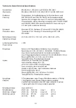
Page 10: ...Potentialfreie Kontakte max m gliche Spannung 24 V DC S13 24 V S23 GND S14 S24 Relais max Strom bei Kurzschlu 85 mA f hrt zum Abfall max Eingangswiderstand zwischen S13 S14 S23 S24 150 Reset AZR31R2 2...

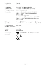
Page 11: ...mm Litze mit H lse DIN 46228 min 0 1 mm max 1 x 4 mm single wire max 1 x 2 5 mm fine wire with sleeve DIN 46228 max 2 x 1 5 mm fine wire with sleeve DIN 46228 min 0 1 mm Meldungen Gr ne LED f r Steue...

Page 12: ...erungen vorbehalten Stand 2001 07 25 techn changes without prior notice 01 26 0254 1034192 11 02 3 000 wd Elan Schaltelemente GmbH Co KG Ein Unternehmen Im Ostpark 2 35435 Wettenberg Tel 0641 9848 0 F...

Reviews: