7
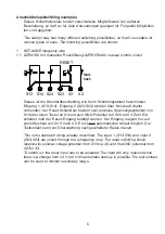
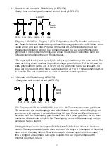
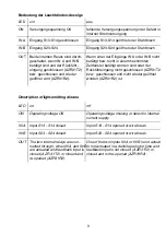
3.1 Schutztür mit manueller Rückführung (AZR31R2)
Safety door monitoring with manual control circuit (AZR31R2)
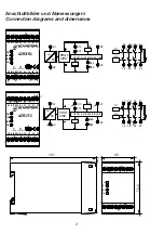
Eingang 1 (S13-S14), Eingang 2 (S23-S24) werden über Tür-Schalter verbunden;
der Reset-Schaltkreis bezieht sein positives Spannungspotential von S13 über einen
Taster an X2 und sein GND-Potential von S23 an X3. Zum Einschalten muß der
Reseteingang betätigt werden. Der Eingang reagiert nur auf einen Wechsel von
24 V nach 0 V. Es ist kein automatischer Anlauf möglich. Der Testkontakt kann zur
Überwachung nachgeschalteter Relais dienen.
The input 1 (S13-S14) and input 2 (S23-S24) are joined through the door switch. The
reset switching circuit receives its positive voltage potential from S13 via X2, and the
GND potential from S23 to X3. To switch on, the reset input has to be actuated. The
input will only respond when there is a change from 24 V to 0 V. No automatic start-up
is possible. The test contact can be used to monitor secondary relays.
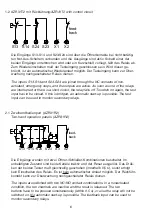
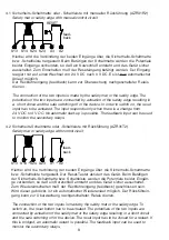
3.2 Schutztür mit Rückführung (AZR31T2)
Safety door with control circuit (AZR31T2)
Die Eingänge S13-S14 und S23-S24 sind über die Türschalter bei nicht geöffneter
Tür verbunden und die Ausgänge sind aktiv. Sobald einer der beiden Eingänge un-
terbrochen wird oder ein Kurzschluß vorliegt, fällt das Relais ab. Zum Wiederein-
schalten muß der Testeingang geschlossen sein. Wird dieser gebrückt, ist ein auto-
matischer Wiederanlauf möglich. Der Testeingang kann zur Überwachung nachge-
schalteter Relais dienen.
Having the door closed, the inputs S13-S14 and S23-S24 are joined via the door
switch. The outputs are active. As soon as one of the relays is interrupted or there is a
short circuit, the relay falls off. To switch on again, the test input has to be closed. If
this is bridged, an automatic start-up is possible. The test input can be used to
monitor secondary relays.
S24
S13 S14
S23
X3
X2
RESET
feed-
back
feed-
back
X1
X2
S24
S13 S14
S23

