28
Installation manual of system “bp408” - The control system “bp408”
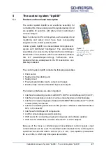
In collaboration with the remote monitoring system of data WinMOS
®
300
(www.WinMOS.de), the availability of the lift can be significantly increased. Using
this system, complete conversion into demand-oriented maintenance is also
possible.
5.2
An overview of the functions of bp408
Individual control system
Group control of up to 8 lifts without separate group computer
128 stops adjustable
SFS – self-propelled control unit
SFR – self-propelled control unit with call storage unit (“taxi control”)
1KS – 1-button collective control system
1KSab – 1-button downward collective control system
1KSauf – 1-button upward collective control system
2KS – 2-button collective control system
Operating data collection: Drives, hours, faults, notifications
Cable elevator: pole-changing, single-rotating, double-rotating, frequency
converter
Hydraulic lift: Star-delta and direct start-up, valve control, soft start, frequency
converter
PTC thermistor monitoring integrated for drive motor
Safety circuit monitoring unit integrated
(standard 230 V AC, optional 48 V AC/DC or 110 V AC)
Main contactor activation 230 V AC integrated
Safety circuit (SMZ) integrated
Inputs and outputs integrated for all standard requirements
Positive switching logic (24 V DC)
Outputs protected against overload
Diagnosis of inputs and outputs via LCD or laptop
Diagnosis and configuration of CANopen lift components with CANwizard®
Operator guidance using laptop with WinMOS
®
300 or with Lift2CLOUD
®
Operator guidance with 7 buttons and illuminated, graphic LCDisplay
Local parameterisation using LCD, with mobile phone via Bluetooth™ or WiFi
or laptop
Parameters stored in EEPROM in a fail-safe way (2 complete data records)
Real-time clock integrated
Setup menu and service menu separate
Code lock separately adjustable
Menu guidance in German, English, Dutch and Swedish
Interfaces for DCP, LAN, USB and CANopen lift are integrated
Optional remote diagnosis via modem (USB) or LAN
Floor display of different codes possible (Gray, binary, user-specific)
Drive direction indicator
Minimum load, full load, excess load, useful load in kg
Summary of Contents for bp408
Page 2: ......
Page 24: ...24 Installation manual of system bp408 Safety instructions...
Page 52: ...52 Installation manual of system bp408 The control system bp408...
Page 58: ...58 Installation manual of system bp408 Installation and assembly...
Page 80: ...80 Installation manual of system bp408 Electrical connection...
Page 118: ...Installation manual of system bp408 Appendix 118 Appendix A Menu navigation bp408...
Page 119: ...119 Installation manual of system bp408 Appendix B Update of the firmware via USB stick...


