34
Installation manual of system “bp408” - The control system “bp408”
5.6
Versions of bp408
This installation manual refers to all versions of the control system bp408.
bp408 is available with 48 V AC/DC, 110 V AC and 230 V AC safety circuit input
voltage including safety circuit.
5.7
Brief description of bp408
5.7.1
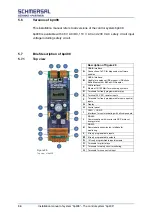
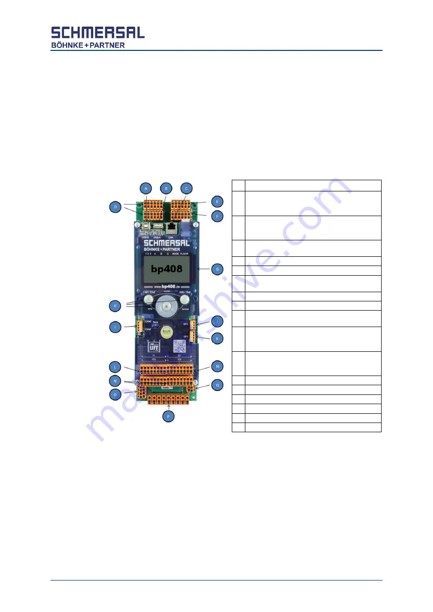
Top view
Description of figure 20
A
USB-B interface:
Connection of a PC for diagnosis or software
updates
B
USB-A interface:
Usable for analogue USB modem, USB sticks,
BöPa Bluetooth or BöPa-WiFi-Adapter
C
LAN interface:
Ethernet 10/100 Mbit for monitoring systems
D
Terminals for freely programmable relay
E
Terminal 24 V DC, resistor inputs
F
Terminals for freely programmable inputs, special
inputs
G
Display
H
Control panel
I
CAN 1 + CAN 2:
Interfaces for communicating with all components
J
RS-485:
Communication with inverter via DCP protocol,
energy meter
K
RS-232:
Remote data transmission, interface for
monitoring
L
8 freely programmable inputs
M
8 freely programmable outputs
N
16 freely programmable inputs/outputs
O
Terminals for pilot relays
P
Terminals for safety circuit monitoring
Q
Terminals for zone switch input
Figure 20:
Top view of bp408
Summary of Contents for bp408
Page 2: ......
Page 24: ...24 Installation manual of system bp408 Safety instructions...
Page 52: ...52 Installation manual of system bp408 The control system bp408...
Page 58: ...58 Installation manual of system bp408 Installation and assembly...
Page 80: ...80 Installation manual of system bp408 Electrical connection...
Page 118: ...Installation manual of system bp408 Appendix 118 Appendix A Menu navigation bp408...
Page 119: ...119 Installation manual of system bp408 Appendix B Update of the firmware via USB stick...


