3
EDR EFR
Operating instructions
Emergency stop command device
EN
3 Mounting
3.1 General mounting instructions
•
Fit the EDR EFR emergency stop actuator in non-actuated
condition by means of the EFM mounting flange, align and tighten
(max. 0.6 Nm).
•
Snap the EFR spring element in the middle position of the EFM
mounting flange (position 3). The EFR spring element is supplied
in tensioned condition.
• The EDRR EFR actuator is latched, i.e. mechanically fixed, to the EFR
spring element by actuation. By rotating to the right and consecutive
pulling, the spring element is retensioned and the emergency stop
command device is brought back to its basic position.
• Snap the EF contact element(s) into position(s) 1 (and/or 2) of the
EFM mounting flange.
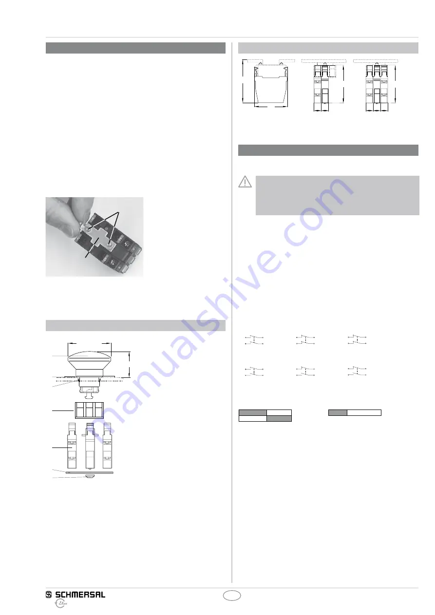
• EFR spring element: to avoid fitting errors, we recommend to fit
the enclosed locking plate (A) by means of both locking rings
(B) 4 mbo 09 after the contacts have been snapped on (see photo).
No special tools are required. This locking plate ensures a proper
fitting and fixation of the contact elements.
B
A
•
The emergency stop device is now ready for operation.
3.2 Dimensions
Dimensions of the EDRR emergency stop command device
Ø 49 (Ø 38,5)
29
a)
b)
c)
d)
e)
f)
g)
1
3
2
a) EDRR. emergency stop actuator
b) Emergency stop label
c) Clamping element
d) ELM mounting flange
e) 2 x EF contact element (Pos. 1 + 2),
1 x EFR spring element (middle, Pos. 3)
f) Locking plate
g) Locking rings 4 mbo 09
Dimensions of the EF contact elements in fitted condition
46
10
10
a)
EFR
EFR
52
52
10 10
10
60
a) Maximum number of contacts (2 contact elements, max. 4 contacts)
4 Electrical connection
4.1 Important notes
The electrical connection may only be carried out by
authorised personnel in a de-energised condition.
At least one contact with positive break must be integrated
in the safety circuit.
After wiring, the contact elements must be cleaned (i.e. remove
excess cables etc.).
The fixing screws of the contact element must be tightened with
0.8 Nm tightening torque.
4.2 Contact variants
The following contact combinations may be used:
•
Screw or plug-in terminals:
– 1 × EF 303 (1 NC/1 NO contact) + 1 × EF 220 (2 NC contacts) or
– 2 × EF 303 (1 NC/1 NO contact) or
•
EFK cage clamp: contact data upon request
11
21
EF 220.1
12
22
11
23
EF 303.1
12
24
31
41
EF 220.2
32
42
31
43
EF 303.2
32
44
51
61
EF 220.3
52
62
51
63
EF 303.3
52
64
4.3 Switch travel
0
6
3
3
0
6
2
EF 303.1/.2/.3
EF 220.1/.2/.3


