background image

Software 


DOC_MAN_MEC_EFAS-CAM_#SEN_#AIN_#V1 


Seite 25 von 56 

Version: 2018 / 02 


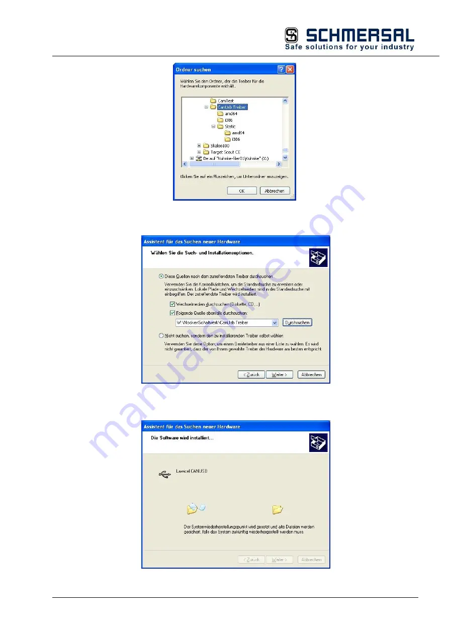
Browse to the folder that you unzipped the downloaded drivers to after, then click on OK. 


Click on "Next" to start the installation process. Skip any security prompts that may appear. 


You will see the following message shortly after the end of the installation. 

Summary of Contents for EFAS CAM Module

Page 1: ...Instruction Manual DOC_MAN_MEC_EFAS CAM_ SEN_ AIN_ V1 Seite 1 von 56 Version 2018 02 Instruction Manual Schmersal EFAS CAM Module...

Page 2: ...c Compatibility 8 2 Introduction 10 2 1 Working principle of cam control units 10 2 1 1 From mechanical cam control units 10 2 1 2 to electronic cam control units 10 2 1 3 Position detection 11 2 1 4...

Page 3: ...ol Track Masks 37 6 4 4 Options Control Options 38 6 5 Device 46 6 5 1 Online Device Online 46 6 5 2 Offline Device Offline 47 6 5 3 Download Device Download 47 6 5 4 Upload Device Upload 47 6 5 5 Era...

Page 4: ...ges against us on whatever grounds are excluded except in instances of deliberate intent or gross negligence on our part 1 2 2 Terms of Delivery The general conditions of sales and service of K A Schm...

Page 5: ...is compulsory 1 3 3 Intended Use Schmersal s products are designed developed and manufactured for standard industrial use They must not be used for any other purposes than the ones specified in the ca...

Page 6: ...ntial consequences of non observance Preventive measures DANGER A DANGER warning makes you aware of an immediately hazardous situation which WILL cause a serious or fatal accident if not observed WARN...

Page 7: ...ency off installations must comply with EN 60204 VDE 0113 They must be operative at any time Safety and precautions regulations for qualified applications have to be complied with Please pay particula...

Page 8: ...to EN 55011 limiting value class A Group 1 Information If the controller is designed for use in residential areas high frequency emissions must comply with limiting value class B as described in EN 5...

Page 9: ...nces caused by motors compressors transfer lines presses ramming machines and vehicles Electromagnetic Interference Consider electromagnetic interference from various local sources motors switching de...

Page 10: ...plications include Presses Fillers Glue application Paper or foil feeding Packaging machines Figure 1 EFAS CAM Module 2 1 Working principle of cam control units When developing the electronic cam cont...

Page 11: ...means of the incremental encoder s reference impulse index 2 1 4 Further benefits of electronics A large number of cams with accurate trigger and release points can be programmed for every output Once...

Page 12: ...thing Connect the EFAS modules to earth by attaching the metal housing to functional earth Since the functional earth connector dissipates HF currents it is of utmost importance for the module s noise...

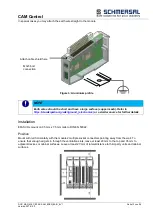
Page 13: ...r further details Installation EFAS I Os mount on 35 mm x 7 5 mm rails to DIN EN 50022 Position Mount with rail horizontally with the modules multiple socket connectors pointing away from the wall To...

Page 14: ...ed Push the top of the module against the mounting wall until it snaps in To interconnect two modules After snapping on the first module to the rail snap on the second module about 1cm away towards th...

Page 15: ...nnector sleeve type 0 14 0 25 0 34 0 50 0 75 1 1 5 Connector sleeve w collar to DIN 46228 4 8 10 8 10 8 10 10 12 12 14 12 15 Connector sleeve w o collar to DIN 46228 1 10 10 Stripped end mm sleeve len...

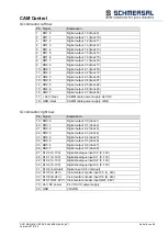
Page 16: ...2 7 track 24 17 24V in out CAM Module power supply 24 VDC 18 GND in out CAM Module power supply GND IO connector right row Pin Signal Explanation 19 DO0 0 Digital output 0 0 track 1 20 DO0 1 Digital...

Page 17: ...EX 79516 1043 MICRO PASS 4WAY CABLE ASSEMBLY 3M You may use a CAN to USB adapter to connect the CAN bus to the programming PC Source http www canusb com You may also need to adapt the D SUB connectors...

Page 18: ...sing no data exchange Pre Op Off green 1 1 Pre operational no data exchange Safe Op Off green 5 1 Safe operation inputs readable Op Green on Operational unrestricted data exchange IO LED The LED label...

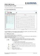
Page 19: ...down to be turned back on until the thermal fuse blows again Power LED The LED labelled Power indicates the state of the I O module s I O power supply State LED flash code Explanation On Green on 24...

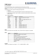
Page 20: ...tates of the outputs tracks bits 0 32 DigitalIn USINT Digital inputs reserved USINT Reserve Position UINT Position Speed UINT Velocity AnalogIn1 UINT Analogue inputs value 0 0 AnalogIn2 UINT Analogue...

Page 21: ...n ON signal received by Ref input DI0 7 resets the counter reading to 0 This is referencing the position if an incremental encoder is used State 1 Bit 1 indicates the state of referencing 4 1 3 4 Cam...

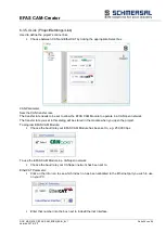
Page 22: ...available in our download area http www schmersal com net efas 5 2 Installation Installations involves running the Setups utility Run the correct CAM Creator setup e g Setup_EFASCAM Creator_V01060101...

Page 23: ...Software DOC_MAN_MEC_EFAS CAM_ SEN_ AIN_ V1 Seite 23 von 56 Version 2018 02 5 3 Start Exit EFAS CAM Creator starts by running EFASCAM exe The last project you used will be loaded...

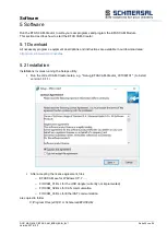
Page 24: ...ivers e g CDM_2 08 14_CANUSB zip from http www can232 com and make a note of the directory that contains the unzipped drivers Plug the USB cable of the CAN to USB adapter into a free USB slot of your...

Page 25: ...on 2018 02 Browse to the folder that you unzipped the downloaded drivers to after then click on OK Click on Next to start the installation process Skip any security prompts that may appear You will se...

Page 26: ...Software DOC_MAN_MEC_EFAS CAM_ SEN_ AIN_ V1 Seite 26 von 56 Version 2018 02 You can now establish an online link between EFAS CAM Creator and the EFAS CAM Module via the CAN to USB adapter...

Page 27: ...more about the number of cams per track the number of tracks per program and the number of programs Refer to Control Options Encoder or CAM for resolution details Decide whether to edit the cams as nu...

Page 28: ...under Control Options Module CAM see 6 4 4 3 This column allows you to pick one of the operating models i e Time time cam or Distance Time cams enable the use of cams with constant times which solely...

Page 29: ...you run Excel OK acknowledges the prompt Open the Excel worksheet and display the sheet containing the cam table In EFAS CAM Creator again click on import from Excel The table will now be imported int...

Page 30: ...eator installation and the EFAS CAM Control while online NOTE EFAS CAM Creator stores all its projects in the above folder If you wish to use the projects elsewhere please copy them from this folder a...

Page 31: ...etails the project management features 6 3 1 new Creates a new project Assign a name to the new project 6 3 2 open Opens a projects and closes the previous project Pick a project from the list in the...

Page 32: ...me creates a copy 6 3 5 Settings 6 3 5 1 Colors Project Settings Colors Use these settings to re design the appearance of your EFAS CAM Creator Color Scheme Choose from Blue Silver and Black to change...

Page 33: ...he CAM array Release Choose between Single or Composite mode o Single Project containing a single EFAS CAM Module o Composite Project containing up to 8 EFAS CAM Modules 6 3 5 3 Project Project Settin...

Page 34: ...le to operate in a CANopen network The transfer rate you set in this dialog will be stored in the module when you open the project To program EFAS CAM Module Choose the baud rate your EFAS CAM Module...

Page 35: ...or later with reference to the actual speed i e cams have to be moved Example of an encoder with 360 increments revolution One revolution is equivalent to 360 increments A cam triggers at 25 and relea...

Page 36: ...the actual speed Tick the boxes in the table rows you use Set the speeds at which a change of program should occur Allocate the programs The picture below is just an example of the following settings...

Page 37: ...alue into the table 6 4 3 Track Masks Control Track Masks To mask tracks You may use a module s digital inputs to disable mask any of the tracks In other words if the digital inputs DI have been alloc...

Page 38: ...N_ AIN_ V1 Seite 38 von 56 Version 2018 02 6 4 4 Options Control Options This section details how to set up the project options The screen looks like the example below if you set option Project Settin...

Page 39: ...tly not implemented See section 1 for an example NOTE Absolute CAN Remember that an Absolute CAN Encoder always connects to the CAN master and that the EFAS CAM Modules then need to link in via EtherC...

Page 40: ...ical conditions resolution and rotational speed of your application Cycle Time Time the controller needs to detect the speed You can set the time to anything between 10 ms and 1000 ms The module count...

Page 41: ...e ID You need to assign a node ID CAN address to the EFAS CAM Module before you can add it to a CANopen network The node ID you set in this dialog will be stored in the module memory when you upload t...

Page 42: ...er revolution as used for cam programming It sets the CAM array s X axis The encoder resolution is the number of pulses or encoder positions per revolution Incremental encoders internally always apply...

Page 43: ...Divide this number by 4 and you will get the required encoder resolution NOTE Absolute EtherCAT encoder If you are using an Absolute EtherCAT encoder changing the module resolution will just affect th...

Page 44: ...r computation Enabled Tick this box to enable dead time compensation Mode Dead time compensation mode cyclic cyclic calculation of dead times i e after every clock pulse see Options Encoder Cycle Time...

Page 45: ...table Use the Speed Change Over dialog to set the basic properties Speed Change Over Enabled Tick this box to run the cam programs with reference to the actual speed Hysteresis Permanent changes of c...

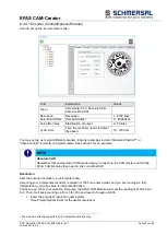
Page 46: ...he track masking table set up under Control Track Mask 6 4 3 Track Masks 6 5 Device This section details the EFAS CAM Creator s online functions 6 5 1 Online Device Online Use this option to enable th...

Page 47: ...6 3 5 4 Link 6 5 3 Download Device Download This function uses the online link to download the cam project from the programming PC to the EFAS CAM Module 6 5 4 Upload Device Upload This function uses...

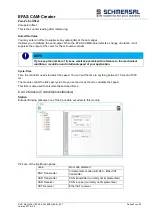
Page 48: ...ol Set Reference Click on this icon to set the position to zero Status Device Data 3 In reverse all EFASCAM module calculations are off Term Explanation Enabled Outputs enabled Referenced Counter refe...

Page 49: ...e the following settings NOTE If you set the position in CODESYS only interim values will not be interpolated i e cams might be skipped This can only be avoided by setting the speed Remember to set th...

Page 50: ...AM Modules 2 You will still see all 8 modules but only two of them will be needed for the remaining settings Set both EFAS CAM Control Modules Encoder Binding to 1 and the Mode to CAT Receiver Set the...

Page 51: ...to actually process every xth value you must run CODESYS and divide its encoder setting by x In this case the resolution is set to 512 ticks which means that you will also have to divide CODESYS encod...

Page 52: ...ering edge The application currently supports 5 time cams per cam program The example below uses time cams on tracks 22 24 31 and 32 The time cams on tracks 31 32 start at 20 ticks and go on for 500 m...

Page 53: ...0F28234 ASIC ET1200 Fieldbus1 system EtherCAT 100 Mbps EtherCAT file SchmersalEFASModulesAll xml Connector 10 pole system plug in side wall Terminating module not required Power supply from EtherCAT c...

Page 54: ...R 36POLE 20PCS 103016725 EFAS SHIELD CONNECTION CLAMP 2x8MM 103016717 EFAS SHIELD CONNECTION CLAMP 1x14MM 103016718 8 3 References Instruction Manual EFAS Modules DOC_MAN_MEC_EFAS IO MODULES_ SEN_ AIN...

Page 55: ...Appendix DOC_MAN_MEC_EFAS CAM_ SEN_ AIN_ V1 Seite 55 von 56 Version 2018 02 8 4 Declaration of conformity...

Page 56: ...site to find a comprehensive overview of our sales and service network including all the relevant addresses Feel free to also contact us at our headquarters 8 5 1 Wuppertal Headquarters K A Schmersal...

Reviews: