CAM Control
DOC_MAN_MEC_EFAS-CAM_#SEN_#AIN_#V1
Seite 12 von 56
Version: 2018 / 02
3
Hardware
3.1
Mechanical design
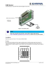
The picture below illustrates the basic layout of the EFAS modules:
The housing mount consists of an aluminium profile with an integral snap-on device used to snap the module
to a 35mm DIN rail. The housing trough including the optical fibres for the status indicators, the side face and
the front is made of plastic and contains the module. The optical fibres for the signal state indicators (LEDs)
are located next to the spring-assisted combi plug. They slightly protrude from the housing and allow a clear
diagnosis at a glance.
Earthing
Connect the EFAS modules to earth by attaching the metal housing to functional earth.
Since the functional earth connector dissipates HF currents, it is of utmost importance for the module's noise
immunity.
HF interference is dissipated from the electronics board to the metal housing. The metal housing therefore
needs to be suitably connected to a functional earth connector.
You will normally have to ensure that
the connection between module housing and DIN rail conducts well,
the connection between DIN rail and switching cabinet conducts well,
the switching cabinet is safely connected to earth.
Figure 2 Module layout
Unlock button
Status LEDs
Shield-to-housing
mount connector
Module lock and E-
bus
DIN rail mount and
functional earth
Ventilation slots
Signal state indicators
(LEDs)
Grip
Label clip
Slot for spring-
assisted combi
plug


