5
MZM 100
MZM 100 B
Operating instructions
Solenoid interlock
EN
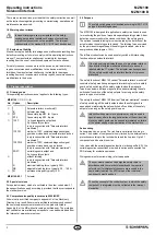
5. Operating principles and latching force adjustment
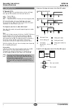
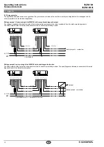
5.1 Mode of operation of the safety outputs
- of MZM 100 variant "Solenoid interlock monitored"
The safety outputs are enabled, when the following conditions are met:
• the actuator has been detected and
• the interlock is locked, the magnetic force is > 500 N
The unlocking of the solenoid interlock causes the safety outputs to be
disabled within the risk time As long as the actuator is present on the
solenoid interlock, the unlocked solenoid interlock can be locked again
In that case, the safety outputs are re-enabled
The latching force F is permanently measured and checked In this way,
soiling of the solenoid interlock can be detected If the latching force
drops below 500 N, the release signal for the safety outputs Y1 / Y2 is
not given
- of MZM 100 B variant "Actuator monitored"
The safety outputs are enabled, when the following conditions are met:
• the actuator has been detected, the latching force is active and
• locking with magnetic force > 500 N possible
Due to the permanent monitoring of the closed magnetic circuit, the
safety outputs Y1/Y2 are only enabled during the latching, when the
magnetic circuit is properly closed and the latching force can also be
obtained when activated If the metal surfaces are soiled or damaged,
the enabling signal is not transmitted
The unlocking of the MZM 100 B does not lead to a switch-off.
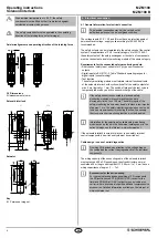
Violent separation of solenoid interlock and actuator
(only in connection with "Solenoid interlock monitored")
The solenoid interlock has a latching force F of 500 N
When the actuator and the interlock are separated in an
unauthorized and violent way, the safety guard is opened
and the enabling paths are switched off within 150 ms
This is signalled through the yellow and red LED blinking
alternatively To bring the system back in operational
condition, the safety guard needs to be closed first and the
solenoid control must be switched off and back on; the yellow
and red LED now are blinking simultaneously With the safety
guard closed, an anti-tampering period of 10 minutes must
be waited until the LEDs go out Now, the system is back
operational after the soilenoid control has been switched off
and back on (The actuator nor the solenoid interlock are
damaged!)
5.2 Description of the latching force adjustment
The latching force of the MZM 100 with ordering suffix -RE can be set in
8 steps of approx 10 N each within a range of approx 30 N to approx
100 N To this end, the adjustment target MZM 100 TARGET is used
directly on the fitted MZM 100
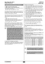
Adjustment of the latching force
1) Open the safety guard and isolate the MZM 100 from the voltage
supply Either switch off the voltage supply or pull out the connector
2) Put the adjustment target with the active side on the identification
plate of the MZM 100
3) Switch the voltage supply of the MZM 100 back on and wait at least
10 seconds before removing the adjustment target The component
searches for the adjustment target When the adjustment mode is
active, the safety outputs remain disabled
4) Remove the adjustment target again from the component
The yellow LED of the MZM 100 will repeatedly flash briefly to
show the currently set latching force level (eg 4 flashes = 4th
latching force level approx 60 N)
5) Put the adjustment target approx 1 second back on the solenoid
interlock with the safety guard open to gradually increase the latching
force by steps of approx 10 N each The number of flashes will
increase accordingly
The modified latching force can be checked directly on the safety
guard If necessary, the latching force can be increased by another
step When latching force level 8 is reached, level 1 will be activated
when the adjustment target is placed back on the component
6) Switch off the voltage supply of the MZM 100 once more to
permanently save the chosen latching force
When the component is switched off, the adjustment mode is quit
After the voltage supply is switched back on, the MZM 100 is ready for
operation
Latching force indication
If the voltage supply of the MZM 100 B is switched on when the
safety guard is open, the yellow LED will show the set latching force for
10 seconds by means of repeated brief flashes (eg 4 × flashes = 4th
latching force level approx 60 N)
Description of the latching force adjustment for the MZM 100-...-SD
with serial diagnostic function
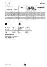
The latching force can be adjusted through the latching force bits 1-3
of the request byte in 8 steps within a range of 30 … 100 N (45 115 N
with permanent magnet)
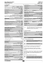
Latching force bit
Latching force RE
Latching force REM
3
2
1
0
0
0
approx 30 N
approx 45 N
0
0
1
approx 40 N
approx 55 N
0
1
0
approx 50 N
approx 65 N
0
1
1
approx 60 N
approx 75 N
1
0
0
approx 70 N
approx 85 N
1
0
1
approx 80 N
approx 95 N
1
1
0
approx 90 N
approx 105 N
1
1
1
approx 100 N
approx 115 N
The actual latching forces may deviate from the specified
values owing to the different influences (eg angled position
of actuator, contamination or damage to metal surface, etc)
When the guard system is opened for the first time from the
locked status, higher latching forces may be experienced on
account of residual magnetism


