
11
MZM 100
MZM 100 B
Operating instructions
Solenoid interlock
EN
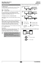
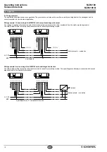
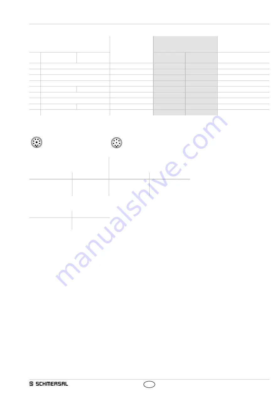
9.2 Wiring configuration and connector accessories
Function safety switchgear
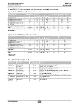
Pin configuration of the
connector
Conductor numbering or
colour code of the
Schmersal connectors
Poss. colour codes of other
customary connectors
with conventional
diagnostic output
with serial
diagnostic function
M23, IP67
M12, IP67 / IP69
to DIN 47100
to
IEC 60947-5-2: 2007
A1
U
e
1
1
WH
BN
X1
Safety input 1
2
2
BN
WH
A2
GND
3
3
GN
BU
Y1
Safety output 1
4
4
YE
BK
OUT
Diagnostic output
SD output
5
5
GY
GY
X2
Safety input 2
6
6
PK
PK
Y2
Safety output 2
7
7
BU
VT
IN
Solenoid control
SD input
8
8
RD
OR
without function
9
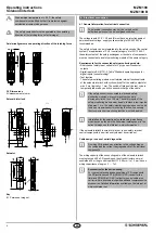
Connector plug ST M23, (8+1)-pole
Connector plug ST2 M12, 8-pole
1
2
9
3
4
5
6
7
8
5
8
4
3
2
1
7
6
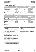
Connecting cables with female connector
IP67, M23, (8+1)-pole - 8 x 0.75 mm²
Connecting cables with coupling (female)
IP67 / IP69, M12, 8-pole - 8 x 0.23 mm²
to DIN 47100
Cable length
Part number
Cable length
Part number
50 m
100 m
101209959
101209958
25 m
50 m
100 m
103011415
103007358
103007359
Connector with plug (female)
IP67, M23, (8+1)-pole - 8 x 0.75 mm²
Design
Part number
with soldering terminals
with crimp terminals
101209970
101209994


