3
MZM 100
MZM 100 B
Operating instructions
Solenoid interlock
EN
2.5 Technical data
General data:
Standards:
IEC 60947-5-1, IEC 60947-5-3, ISO 14119,
ISO 13849-1, IEC 61508
Material of the housings:
Plastic, glass-fibre reinforced thermoplastic,
self-extinguishing
Working principle:
inductive
Coding level according to ISO 14119:
low
Response time:
≤ 150 ms
Duration of risk:
< 150 ms
Time to readiness:
< 4000 ms
Actuator:
MZM 100-B11
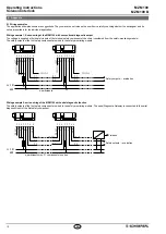
Series-wiring:
Unlimited number of components,
please observe external cable protection,
max 31 components in case of serial diagnostics
Length of the sensor chain:
max 200 m;
- Note:
Cable length and cable section alter the voltage drop
depending on the output current
Mechanical data:
Execution of the electrical connection:
- ST:
M23 connector, (8+1) poles,
- ST2:
M12 connector, 8 poles
Tightening torque of the fixing screws:
8 N
m
Electrically adjustable latching force (RE), typically:
30 N … 100 N
Permanent magnet (M), typically:
15 N
Holding force F
max
typically:
750 N
Holding force F guaranteed:
500 N
Mechanical life:
≥ 1,000,000 operations
(for safety guards ≤ 5 kg and
actuating speed ≤ 0.5 m/s)
Switching distances to IEC 60947-5-3:
Assured switching distance s
ao
:
0 mm
Assured switch-off distance s
ar
:
1 mm
Ambient conditions:
Ambient temperature:
−25 °C … +55 °C
Storage and transport temperature:
−25 °C … +85 °C
Relative humidity:
30% … 95%,
no condensation, no icing
Protection class:
IP65 / IP67
Protection class:
III
Resistance to shock:
30 g / 11 ms
Switching frequency:
1 Hz
Resistance to vibration:
10 150 Hz, amplitude 035 mm / 5 g
Insulation values to IEC 60664-1:
- Rated insulation voltage U
i
:
32 VDC
-
Rated impulse withstand voltage U
imp
:
08 kV
-
Over-voltage category:
III
-
Degree of pollution:
3
Switching frequency:
1 Hz
Electrical data:
Operating voltage U
B
:
24 VDC −15% / +10%
(stabilised PELV units to IEC 60204-1)
Operating current device:
max 06 A
- Note:
plus current through the safety outputs
Magnet switch-on time ED:
100 %
Rated operating voltage U
e
:
24 VDC
Rated operating current I
e
:
1 A
Required rated short-circuit current:
100 A
Device fuse rating:
2 A
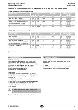
Electrical data – Safety inputs:
Safety inputs:
X1 and X2
Switching thresholds:
− 3 V … 5 V (Low),
15 V … 30 V (High)
Accepted test pulse duration on input signal:
≤ 1.0 ms
- With test pulse interval of:
≥ 100 ms
Classification:
ZVEI CB24I
Countersink:
C1
Source:
C1
C2
C3
Electrical data – Safety outputs:
Safety outputs:
Y1 and Y2
Switching elements:
normally open function, 2 channel,
OSSD, p-type
Fuse rating:
short-circuit proof
Utilisation category:
DC-13: U
e
/I
e
: 24 VDC / 025 A
Rated operating current I
e
:
each max 025 A
Leakage current I
r
:
≤ 0.5 mA
Voltage drop U
d
:
< 1 V
Test pulse duration:
≤ 1.0 ms
Test pulse interval:
1000 ms
Classification:
ZVEI CB24I
Source:
C1
Countersink:
C1
Electrical data – Diagnostic output:
Diagnostic output:
OUT
Switching element:
p-type, short-circuit proof
Utilisation category:
DC-13: Ue/Ie: 24 VDC / 005 A
Wiring capacitance for serial diagnostics:
max 50 nF
Electrical data – Magnet control:
Magnet control:
IN
Switching thresholds:
− 3 V … 5 V (Low),
15 V … 30 V (High)
Current consumption per input:
typical10 mA / 24 V, dynamic 20 mA
Accepted test pulse duration on input signal:
≤ 5.0 ms
- With test pulse interval of:
≥ 40 ms
Classification:
ZVEI CB24I
Countersink: C0
Source:
C1
C2
C3
LED status display:
green LED:
Supply voltage
yellow LED
:
Device condition
red LED:
Internal device error
Use isolated power supply only If the cable and connector
assembly is not listed for Type 12 or higher, then the device
shall be used in a Type 1 environment only
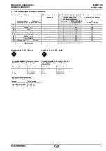
2.6 Safety classification
Standards:
ISO 13849-1, IEC 61508
PL:
e
Control Category:
4
PFH:
354 x 10
-9
/ h
SIL:
suitable for SIL 3 applications
Service life:
20 years
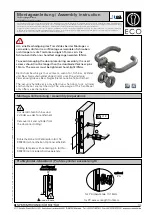
3. Mounting
3.1 General mounting instructions
Please observe the relevant requirements of the stan-
dards ISO 12100, ISO 14119 and ISO 14120
The solenoid interlock must be used as an end stop
Any mounting position The system must only be operated with an
angle of ≤ 2° between the solenoid interlock and the actuator.
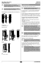
For fitting the solenoid interlock and the actuator, two mounting
holes for M6 screws with washers (washers included in delivery) are
provided
After fitting, the mounting holes can be sealed by means of the supplied
plugs The plugs serve as a means of sealing the assembly openings
and are also suitable to prevent against tampering with the screw
connection
Minimum distance between two devices: 100 mm
The actuator must be permanently fitted to the safety guards
and protected against displacement by suitable measures
(eg tamperproof screws, gluing, drilling of the screw heads)