background image

6

Operating instructions
Passive distribution module

PDM-IOP-4CC-IOP

EN

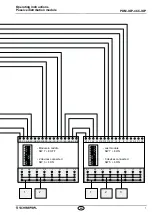
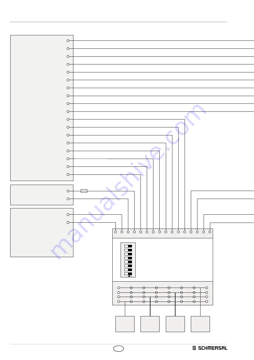
4.7  Wiring example


Y2 Y1 A2 A1 O4 O3 O2 O1 I4

I3

I2

I1 A1 A2 X1 X2

A1

A2

X1

X2

I

O

Y1

Y2

Safety IN 2

Safety IN 1

0 VDC

+24 VDC

IN 9

IN 8

IN 7

IN 6

OUT 9

OUT 8

OUT 7

OUT 6

10A

O

N

1

8
7
6
5
4
3
2

IN 5

IN 4

OUT 5

OUT 4

IN 3

IN 2

IN 1

OUT 3

OUT 2

OUT 1

1

2

3

4

PLC

Power  
supply

Safety  
monitoring

Safety  
switchgear

-  Module in middle  

SW 7 + 8 OFF

-  4 devices connected  

SW 1 - 6 OFF

SW 7 + 8 OFF

SW 3 + 4 ON

SW 7 + 8 ON

SW 5 + 6 ON

Summary of Contents for PDM-IOP-4CC-IOP

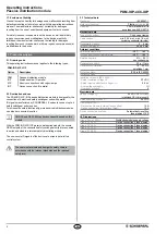
Page 1: ...nufacturer Detailed information regarding the range of applications can be found in the chapter Product description 1 5 General safety instructions The user must observe the safety instructions in thi...

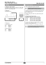
Page 2: ...e secure OSSD outputs of the connected safety switchgear units are connected in series and wired to a relevant safety monitoring module The non secure IO signals of the devices are wired in parallel t...

Page 3: ...ed condition It is possible to connect wires with and without conductor ferrules with a wire cross section of 0 25 mm to 1 5 mm to the terminals of the passive distribution module The supply voltage o...

Page 4: ...pin device connection Pin assignment of safety switchgear connection Function safety switchgear Pin assignment of connector plug or conductor numbers Colour code of the Schmersal connector to DIN 4710...

Page 5: ...1 24 VDC device supplied I Solenoid control O Diagnostic output A2 0 VDC device supplied X1 Safety input 1 X2 Safety input 2 Pin assignment of safety switchgear 2 Y1 Safety output 1 Y2 Safety output 2...

Page 6: ...I2 I1 A1 A2 X1 X2 A1 A2 X1 X2 I O Y1 Y2 Safety IN 2 Safety IN 1 0 VDC 24 VDC IN 9 IN 8 IN 7 IN 6 OUT 9 OUT 8 OUT 7 OUT 6 10A O N 1 8 7 6 5 4 3 2 IN 5 IN 4 OUT 5 OUT 4 IN 3 IN 2 IN 1 OUT 3 OUT 2 OUT 1...

Page 7: ...O3 O2 O1 I4 I3 I2 I1 A1 A2 X1 X2 A1 A2 X1 X2 I O Y1 Y2 Y2 Y1 A2 A1 O4 O3 O2 O1 I4 I3 I2 I1 A1 A2 X1 X2 A1 A2 X1 X2 I O Y1 Y2 O N 1 8 7 6 5 4 3 2 O N 1 8 7 6 5 4 3 2 1 2 1 2 3 Module in middle SW 7 8...

Page 8: ...ntenance If installed correctly and used as intended the passive distribution module requires no maintenance 6 Disassembly and disposal 6 1 Disassembly The passive distribution module may only be remo...

Reviews: