2
Operating instructions
Passive distribution module
PDM-IOP-4CC-IOP
EN
1.7 Exclusion of liability
We shall accept no liability for damages and malfunctions resulting from
defective mounting or failure to comply with this operating instructions
manual. The manufacturer shall accept no liability for damages
resulting from the use of unauthorised spare parts or accessories.
For safety reasons, invasive work on the device as well as arbitrary
repairs, conversions and modifications to the device are strictly
forbidden; the manufacturer shall accept no liability for damages
resulting from such invasive work, arbitrary repairs, conversions and/or
modifications to the device.
2. Product description
2.1 Ordering code
This operating instructions manual applies to the following types:
PDM-IOP-4CC-IOP
Option
Description
PDM
Passive distribution module
IOP
Evaluation side: IO parallel
4CC
4 device connections with cage clamps
IOP
Device connection: IO parallel
2.2 Destination and use
The PDM-IOP-4CC-IOP passive distribution module is designed for the
connection of 4 electronic safety switchgear units with parallel
IO signals manufactured by SCHMERSAL. It serves to connect up to 4
safety switchgear units in series.
To increase the safety functionality, more passive distribution modules
can also be connected in series.
CSS 30- and CSS 180-type devices cannot be used on this
module.
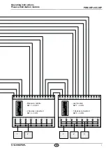
With the PDM-IOP-4CC-IOP passive distribution module, the secure
OSSD outputs of the connected safety switchgear units are connected
in series and wired to a relevant safety-monitoring module.
The non-secure IO signals of the devices are wired in parallel to a
control system.
The user must evaluate and design the safety chain in
accordance with the relevant standards and the required
safety level.
2.3 Technical data
Standards:
IEC 60947-1
Material of housing:
Plastic,
polyamide
66
Mounting:
35 mm standard rail in
accordance with EN 60715
Mechanical data
Type of connection:
Clips, cage clamps
Cable section:
min. 0.25 mm², max. 1.5 mm²
(including conductor ferrules)
De-insulation length:
5 … 6 mm
Actuator tool blade:
3.5 x 0.5 mm
Ambient conditions
Ambient temperature:
−25 °C … +65 °C
Storage and transport temperature:
−40 °C … +85 °C
Relative humidity:
5 % … 95 %,
non condensing
Resistance to shock:
30 g / 11 ms
Resistance to vibration:
10 ... 55 Hz,
amplitude 1 mm
Protection class:
IP00 to IEC 60529
Protection class:
III
Insulation values to IEC 60664-1:
- Rated insulation voltage Ui:
32 VDC
- Rated impulse withstand voltage U
imp
:
0.8 kV
- Over-voltage category:
III
- Degree of pollution:
2
Electrical data
Supply voltage U
B
:
24 VDC -15% / +10%
(stabilised PELV mains unit)
Rated operating voltage U
e
:
24 VDC
Operating current I
e
:
- Distribution module (external fuse needed):
10 A
- Device connection (internal fuse fitted):
1.5 A
Device connection line fuse:
Automatically resetting
fuse element 1.5 A
LED indications
Green “Power” LED:
Distribution module supply voltage
Green “F4” LED:
Device connection 4 fuse element
Green “F3” LED:
Device connection 3 fuse element
Green “F2” LED:
Device connection 2 fuse element
Green “F1” LED:
Device connection 1 fuse element


