3
PDM-IOP-4CC-IOP
Operating instructions
Passive distribution module
EN
3. Mounting
3.1 General mounting instructions
The distribution module is designed to be mounted in a switch cabinet.
The module can be attached to a standard 35 mm rail in accordance
with EN 60715. Any mounting position.
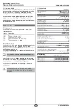
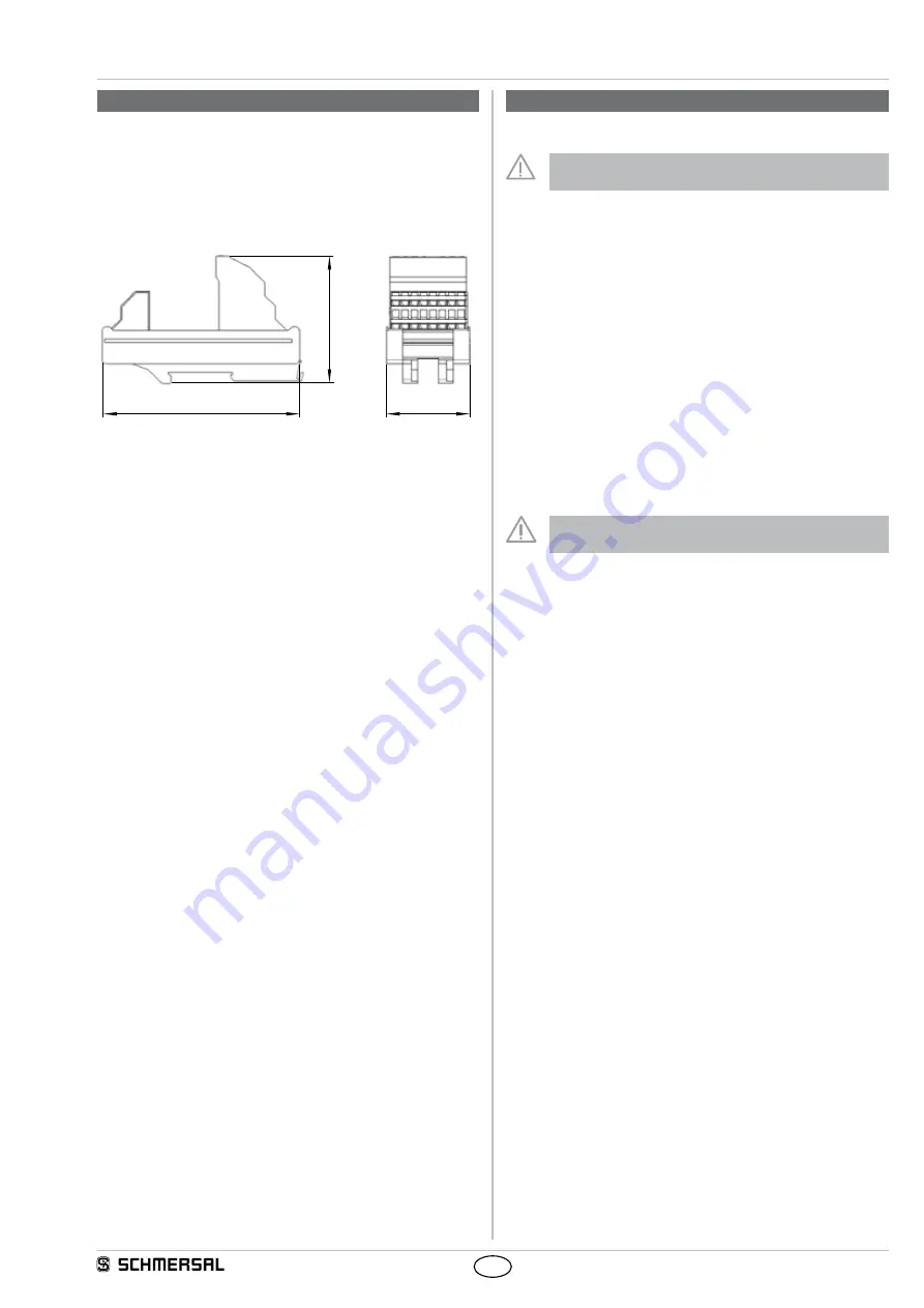
3.2 Dimensions
All measurements in mm.
67,7
45,0
105,4
3.3 Accessories
Pre-wired cable M12, 8 pole
2.5 m
103011415
5.0 m
103007358
10 m
103007359
Pre-wired cable M8, 8 pin
2.0 m
103003638
5.0 m
103003639
10 m
103003640
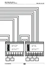
4. Electrical connection
4.1 General information for electrical connection
The electrical connection may only be carried out by
authorised personnel in a de-energised condition.
It is possible to connect wires with and without conductor ferrules with
a wire cross section of 0.25 mm² to 1.5 mm² to the terminals of the
passive distribution module.
The supply voltage of the module is to be protected with a fuse with
a 10 A rating.
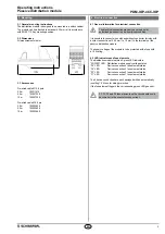
4.2 LED indicators and fuse elements
The distribution module features 5 green LED indicators.
“POWER” LED
Distribution module supply voltage status
“F4” LED
Device connection 4 fuse element status
“F3” LED
Device connection 3 fuse element status
“F2” LED
Device connection 2 fuse element status
“F1” LED
Device connection 1 fuse element status
The 4 device connections are each equipped with an automatically
resetting 1.5 A fuse for wiring protection.
If the fuse element triggers, the corresponding green LED goes out.
F1, F2, F3 and F4 fuse elements on the circuit board could
become hot in the event of excess current.


