4
Operating instructions
Passive distribution module
PDM-IOP-4CC-IOP
EN
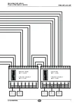
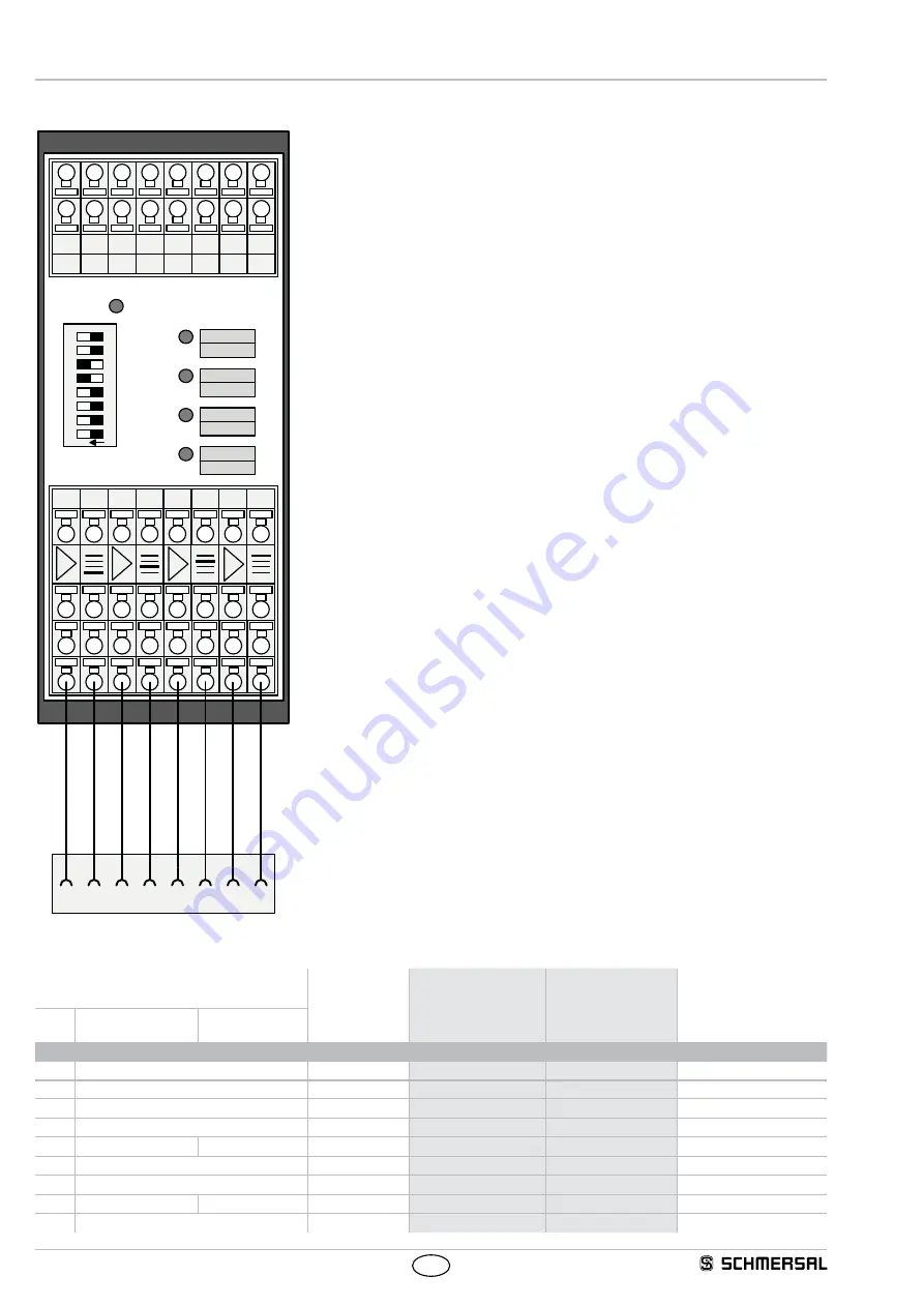
4.3 Pin assignment of module connection
POWER
F4
F3
F2
F1
O
N
1
8
7
6
5
4
3
2
I4
X1
O4
X2
I3
Y1
O3
Y2
I2
A2
O2
A2
I1
A1
O1
A1
Y1 Y2 A1
I
O A2 X1 X2
2
4
3
1
4
7
1
8
5
3
2
6
2 level terminal
Input and output signals of safety switchgear units
Safety signals and supply voltage
4 level terminal
Safety switchgear connection 4
Safety switchgear connection 3
Safety switchgear connection 2
Safety switchgear connection 1
M23 / M12 / M8 8-pin device connection
Pin assignment of safety switchgear connection
Function safety switchgear
Pin assignment of
connector plug
or conductor
numbers
Colour code of the
Schmersal connector
to DIN 47100
Colour code of the
Schmersal connector
Possible colour code of
other commercially availa-
ble connectors, also refer
to IEC 60947-5-2
with conventional
diagnostic output
with serial
diagnostic function
from
part no. 103007xxx
to
part no. 103007xxx
A1
U
e
1
WH
BN
BN
X1
Safety input 1
2
BN
WH
WH
A2
GND
3
GN
BU
BU
Y1
Safety output 1
4
YE
BK
BK
OUT
Diagnostic output
SD output
5
GY
GY
GY
X2
Safety input 2
6
PK
VT
PK
Y2
Safety output 2
7
BU
RD
VT
IN
Solenoid control
SD input
8
RD
PK
or
without function
9


