5
PROTECT-IE
Operating instructions
Input expander module
EN
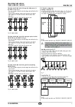
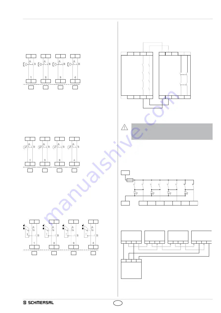
Dual-channel antivalent control of magnetic safety sensors to
IEC 60947-5-3 (see Fig. 7)
• The control system recognises wire breakage and earth faults in the
control circuit.
• Cross-wire shorts between the monitoring circuits are detected.
• If the inputs S1, S3, S5 and S7 are not used, they have to be
bridged to +.
• The unused inputs S2, S4, S6 and S8 remain vacant.
S1
+
S2
Y1
a)
+
S3
+
S4
Y2
+
S5
+
S6
Y3
+
S7
+
S8
Y4
+
Fig. 7 a) signal outputs
Dual-channel antivalent control of an emergency stop circuit to
EN ISO 13850 and EN 60947-5-5 (Fig. 8)
• The control system recognises wire breakage and earth faults in the
control circuit.
• Cross-wire shorts between the monitoring circuits are detected.
• If the inputs S1, S3, S5 and S7 are not used, they have to be
bridged to +.
• The unused inputs S2, S4, S6 and S8 remain vacant.
S1
+
S2
Y1
a)
+
S3
+
S4
Y2
+
S5
+
S6
Y3
+
S7
+
S8
Y4
+
Fig. 8 a) signal outputs
Dual-channel antivalent control of a guard door monitoring
EN 1088 (Fig. 9)
• The control system recognises wire breakage and earth faults in the
control circuit.
• Cross-wire shorts between the monitoring circuits are detected.
• If the inputs S1, S3, S5 and S7 are not used, they have to be
bridged to +.
• The unused inputs S2, S4, S6 and S8 remain vacant.
S1
+
S2
Y1
a)
+
S3
+
S4
Y2
+
S5
+
S6
Y3
+
S7
+
S8
Y4
+
Fig. 9 a) signal outputs
8.3 Actuator configuration
Enabling circuits (Fig. 10)
• All safety-monitoring modules with control category 4 or PLe from the
Schmersal Group with current < 1 A in the monitoring circuit can be
connected to the Protect-IE-02 and Protect-IE-11 devices.
13
23
14
24
S11
S21
S12
S22
13
23
14
24
a)
Protect
IExx
K1
K3
K5
K2
K4
K6
K7
K8
K1
K2
Fig. 10
a) Safety-monitoring module, e.g. SRB 301MC, SRB 301ST, SRB 211ST
The safety-monitoring modules must be suitable for the
signal processing of single- or dual-channel potential-free NC
contacts. The start and actuator configuration must be set up
in accordance with the datasheet.
Signalling outputs (see fig. 11)
• The LED's or the signal outputs indicate that the safety guard or the
emergency stop circuit is opened.
• Both contact circuits of a sensor are monitored.
• If the safety guard or the emergency stop circuit is opened, a 24V
signal is activated at the output concerned (Y1...Y4) and the allocated
LED is lit.
Y1
Y2
Y3
Y4
K3
K5
K1
K7
K4
K6
K2
K8
A1
A2
Fig. 11
Cascading (Fig. 12)
• In this way, up to 20 components can be wired in series. This
corresponds to a signal processing of up to 80 sensors.
13
14
23
24
Pr
otect-IE..
Protect-IE..
Protect-IE..
Protect-IE..
13
14
23
24
13
14
23
24
13
14
23
24
S11
S12
S21
S22
a)
Fig. 12
a) Safety-monitoring module, e.g. SRB 301MC, SRB 301ST, SRB 211ST

