Installation / project planning
Instruction Manual PROTECT-PSC
V 2.6R01 / 04.19
4
–3
Assembly
Select a location which is as far as possible away from the power level and other
disturbing radiation and heat sources of the switch cabinet.
4.1.3
Assembly/dismantling of the individual modules
Assembly / dismantling work may only be performed in a de-energized state.
Assembly
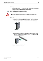
1.
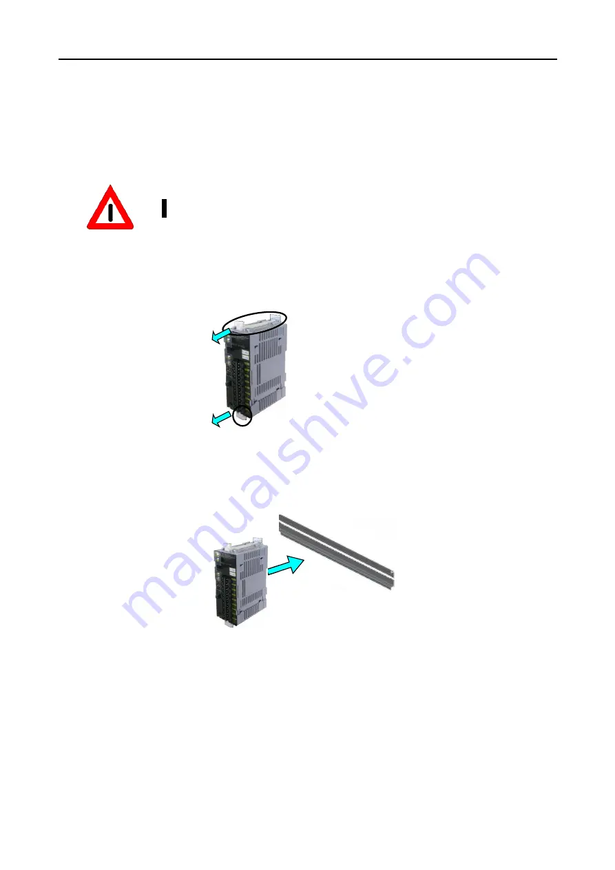
Attach an earthed DIN top hat rail with a maximum distance of the screwed
connection of 10 cm. In order to attach the module to the top hat rail, the
two interlocks must be tightened.
F
F
i
i
g
g
u
u
r
r
e
e
4
4
-
-
2
2
A
A
s
s
s
s
e
e
m
m
b
b
l
l
y
y
o
o
f
f
a
a
m
m
o
o
d
d
u
u
l
l
e
e
(
(
1
1
/
/
3
3
)
)
2.
Then carefully press the module against the top hat rail until a click is heard.
If a further module is to be connected next to it, it must be ensured that the
back plane bus is first installed.
F
F
i
i
g
g
u
u
r
r
e
e
4
4
-
-
3
3
A
A
s
s
s
s
e
e
m
m
b
b
l
l
y
y
o
o
f
f
a
a
m
m
o
o
d
d
u
u
l
l
e
e
(
(
2
2
/
/
3
3
)
)
Summary of Contents for PROTECT-PSC
Page 4: ......
Page 8: ......
Page 112: ......
Page 132: ......
Page 252: ......
Page 265: ...Annex 8 Instruction Manual PROTECT PSC V 2 6R01 04 19 8 5 8 3 EC Type Examination certificate ...
Page 266: ...Annex 8 Instruction Manual PROTECT PSC V 2 6R01 04 19 8 6 8 4 Declarations of conformity W ...
Page 267: ...Annex 8 Instruction Manual PROTECT PSC V 2 6R01 04 19 8 7 8 5 Index ...


