Installation / project planning
Instruction Manual PROTECT-PSC
V 2.6R01 / 04.19
4
–9
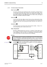
Internal fusing
The CPU and the safe/operational modules, with the exception of the relay module,
have internal fusing which is intended to protect the modules from destruction in
the case of a short circuit. These fuses are not conceived as overload protection
for normal operation. Please observe the prescribed specification for the connec-
tion of the modules. If the internal fuse is destroyed, the module no longer func-
tions. The fuse can be replaced.
4.2.2
Power module
An external pre-fuse of 1.0 A slow blowing is to be incorporated into the supply ta-
bles.
4.2.3
Connecting the CPU module to the gateway
The communication line (SN-I/F) for an additional control of the PSC-U-G gateway
series must meet the following requirements:
•
Cross-section of at least 0,25mm²
•
Twisted in pairs ( >3 times per metre)
•
Shielded braiding of copper wire with at least 80% cover
•
Wave resistance 100 - 180 Ohm
Recommended: Schmersal ZUBEH-PROTECT-PSC-CABLE-UNI-GATEWAY,
Art. No. 101209631
When connecting, pay attention to the correct polarity of the terminals L+ and L-.
The shielding must be put on both sides (PROTECT-PSC and PSC-U-G series)
onto the terminal 0V. See also the PSC-U-G operating instructions.
The SN I/F cable should be less than 3m.
If available, the cable included with the Gateway shall be used.
Refer to information in Chapter 3.5.2 for power supply of the gateway.
Summary of Contents for PROTECT-PSC
Page 4: ......
Page 8: ......
Page 112: ......
Page 132: ......
Page 252: ......
Page 265: ...Annex 8 Instruction Manual PROTECT PSC V 2 6R01 04 19 8 5 8 3 EC Type Examination certificate ...
Page 266: ...Annex 8 Instruction Manual PROTECT PSC V 2 6R01 04 19 8 6 8 4 Declarations of conformity W ...
Page 267: ...Annex 8 Instruction Manual PROTECT PSC V 2 6R01 04 19 8 7 8 5 Index ...

