Programming / parameter assignment
Instruction Manual PROTECT-PSC
V 2.6R01 / 04.19
6-22
Ladder diagram
The program is actually created in the LD window. The symbols are inserted via
the ‘contacts’ tool bar or property dialogue. The program is executed block by block
from the top to the bottom and once it reaches the bottom end, starts from the top
again. Within a block the individual instructions are processed from left to right. On-
ly contacts can be inserted on the left hand side. Coils and functions are always ar-
ranged to the far right. Every block has a block number which represents a check
step during logical program checking (see Chapter 6.13.2 / 6-86) . A comment can
be entered for every block and for every contact/coil/function. Block comments
(maximum 4 x 50 characters long) are displayed directly in the LD window and
contact comments (maximum 100 characters long) in their own window. The con-
tact comments window can be displayed/concealed with the tool button
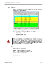
The display of the ladder diagram differs as follows for the PS and PN program:
•
PS program : background WHITE
•
PN program
: background GREEN
F
F
i
i
g
g
u
u
r
r
e
e
6
6
-
-
1
1
9
9
P
P
S
S
l
l
a
a
d
d
d
d
e
e
r
r
d
d
i
i
a
a
g
g
r
r
a
a
m
m
w
w
i
i
n
n
d
d
o
o
w
w
Summary of Contents for PROTECT-PSC
Page 4: ......
Page 8: ......
Page 112: ......
Page 132: ......
Page 252: ......
Page 265: ...Annex 8 Instruction Manual PROTECT PSC V 2 6R01 04 19 8 5 8 3 EC Type Examination certificate ...
Page 266: ...Annex 8 Instruction Manual PROTECT PSC V 2 6R01 04 19 8 6 8 4 Declarations of conformity W ...
Page 267: ...Annex 8 Instruction Manual PROTECT PSC V 2 6R01 04 19 8 7 8 5 Index ...


