Programming / parameter assignment
Instruction Manual PROTECT-PSC
V 2.6R01 / 04.19
6-60
Enable
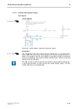
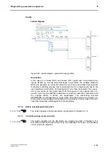
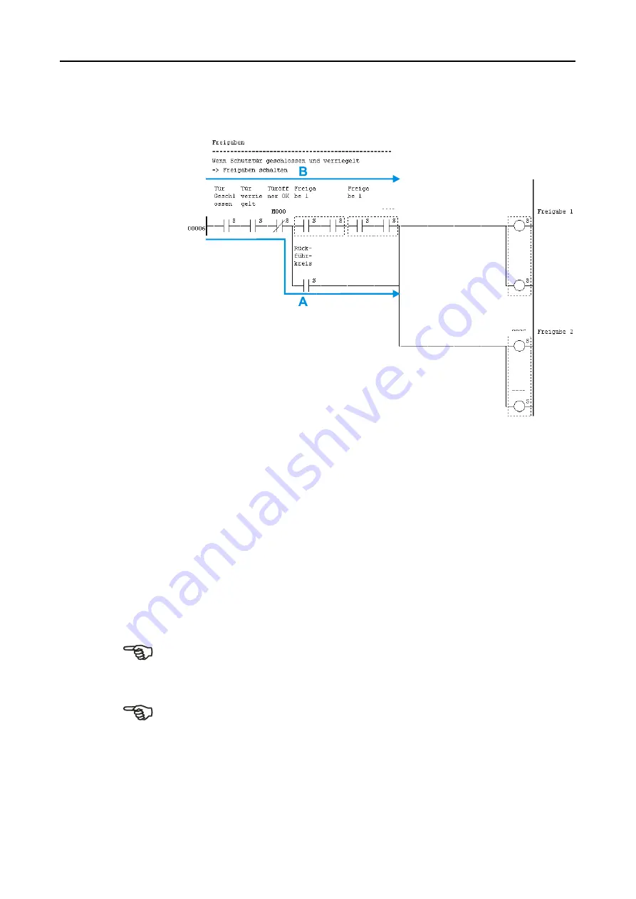
Ladder diagram
F
F
i
i
g
g
u
u
r
r
e
e
6
6
-
-
4
4
6
6
L
L
a
a
d
d
d
d
e
e
r
r
d
d
i
i
a
a
g
g
r
r
a
a
m
m
–
–
g
g
u
u
a
a
r
r
d
d
w
w
i
i
t
t
h
h
l
l
o
o
c
c
k
k
i
i
n
n
g
g
(
(
e
e
n
n
a
a
b
b
l
l
e
e
)
)
Description
In the case of a closed (I010) and locked (I011) guard and non-actuated door
opener (M000) as well as closed feedback circuit (I008) the enables (Q020 to
Q023) are activated via connection branch A. As soon as an actuator has ended its
mechanical switching process, this connecting branch no longer exists due to the
open feedback circuit (I008). Connecting branch A is thus interrupted. The connec-
tion is now made via the closed branch B. If the guard is now opened and a re-
quest to open the door (M000) is detected, connection branch B is interrupted and
the enables (Q020 to Q023) are deactivated. The interlocking solenoid
(Q00A/Q00B) is not triggered any longer either. This state remains in existence un-
til the guard is closed again and locked and the feedback circuit is closed. The pro-
cess described above starts again from the beginning.
6.11.6
Safety solenoid-operated switch
The ladder diagram and the description are provided in Chapter 6.11.4.
6.11.7
Current-sourcing semi-conductor
The ladder diagram and the description are similarly provided in Chapter 6.11.4
(but without start and reset circuit). Only the addresses for sensor and feedback
circuit need to be adjusted.
I010
I011
Q022
Q023
I008
Q020
Q021
Q020
Q021
Q022
Q023
Summary of Contents for PROTECT-PSC
Page 4: ......
Page 8: ......
Page 112: ......
Page 132: ......
Page 252: ......
Page 265: ...Annex 8 Instruction Manual PROTECT PSC V 2 6R01 04 19 8 5 8 3 EC Type Examination certificate ...
Page 266: ...Annex 8 Instruction Manual PROTECT PSC V 2 6R01 04 19 8 6 8 4 Declarations of conformity W ...
Page 267: ...Annex 8 Instruction Manual PROTECT PSC V 2 6R01 04 19 8 7 8 5 Index ...

