Instruction Manual PROTECT-PSC
V 2.6R01 / 04.19
3
–29
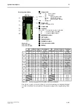
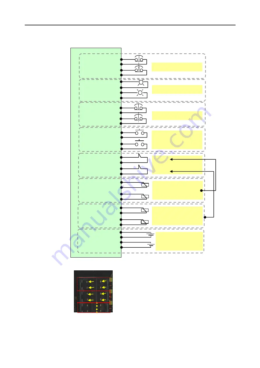
PSC-CPU-MON / PSC-CPU-OP-MON terminal diagram (Example)
Terminal block pin number mapping
F
F
i
i
g
g
u
u
r
r
e
e
3
3
-
-
7
7
P
P
S
S
C
C
-
-
C
C
P
P
U
U
-
-
M
M
O
O
N
N
/
/
P
P
S
S
C
C
-
-
C
C
P
P
U
U
-
-
O
O
P
P
-
-
M
M
O
O
N
N
t
t
e
e
r
r
m
m
i
i
n
n
a
a
l
l
p
p
l
l
a
a
n
n
C
O
M
+
B
-
I
N
0
S-STOP input 1
C
O
M
+
B
-
I
N
1
A
-
I
N
1
C
O
M
-
A
-
O
U
T
1
O
U
T
-
P
B
-
O
U
T
1
O
U
T
-
P
S1
S2
RB
S/R
B
-
O
U
T
0
O
U
T
-
P
LM
O-P
S-Stop-1A 1
IN-COM+
3
IN_COM-
2
S-Stop-1B
4
Status displays
Ready
1
OUT_COM- 2
Master-On 3
OUT_COM-
4
S-STOP input 2
S-Stop-2A 1
IN-COM+
3
IN_COM-
2
S-Stop-2B 4
Start
1
IN-COM+
3
2
Reset
4
Start
Reset
MS1/2-RB
1
IN-COM+
3
2
MS3/4-RB
4
Read-back inputs
MS1
1
OUT_COM- 2
MS2
3
OUT_COM- 4
Semi-conductor output
MS3
1
OUT_COM- 2
MS4
3
OUT_COM- 4
Semi-conductor output
M1
M2
IN_P+
1/3
IN_P-
2/4
OUT_P+ 1/3
OUT_P- 2/4
Power supply
inputs
outputs
I-P
The NC con-
tacts of the
actors are
usually con-
trolled here
by the cor-
responding
semi-
conductor
output
pin No
.
not use
3
1
2
4
3
1
2
4
Summary of Contents for PROTECT-PSC
Page 4: ......
Page 8: ......
Page 112: ......
Page 132: ......
Page 252: ......
Page 265: ...Annex 8 Instruction Manual PROTECT PSC V 2 6R01 04 19 8 5 8 3 EC Type Examination certificate ...
Page 266: ...Annex 8 Instruction Manual PROTECT PSC V 2 6R01 04 19 8 6 8 4 Declarations of conformity W ...
Page 267: ...Annex 8 Instruction Manual PROTECT PSC V 2 6R01 04 19 8 7 8 5 Index ...

