Instruction Manual PROTECT-PSC
V 2.6R01 / 04.19
3
–52
Housing description
F
F
i
i
g
g
u
u
r
r
e
e
3
3
-
-
2
2
6
6
P
P
S
S
C
C
-
-
S
S
-
-
S
S
T
T
P
P
-
-
E
E
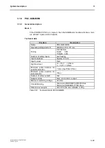
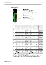
I/O
address
Pin
no.
name
Terminal
name
I/O
address
Pin
no.
name
Terminal
name
S1
00
1
0
S-Stop-1A
01
2
-
IN_COM-
00
3
+
01
4
1
S-Stop-1B
S2
02
1
2
S-Stop-2A
03
2
-
IN_COM-
02
3
+
03
4
3
S-Stop-2B
RB
04
1
4
MS1/2-RB
05
2
+
04
3
+
05
4
5
MS3/4-RB
M1
06
1
6
MS1
06
2
-
OUT_COM-
07
3
7
MS2
07
4
-
OUT_COM-
M2
08
1
8
MS3
08
2
-
OUT_COM-
09
3
9
MS4
09
4
-
OUT_COM-
I-P
1
I+
IN_P+
2
I-
IN_P-
3
I+
IN_P+
4
I-
IN_P-
O-P
1
O+
OUT_P+
2
O-
OUT_P-
3
O+
OUT_P+
4
O-
OUT_P-
T
T
a
a
b
b
l
l
e
e
3
3
-
-
2
2
1
1
T
T
e
e
r
r
m
m
i
i
n
n
a
a
l
l
d
d
e
e
s
s
i
i
g
g
n
n
a
a
t
t
i
i
o
o
n
n
P
P
S
S
C
C
-
-
S
S
-
-
S
S
T
T
P
P
-
-
E
E
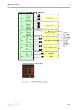
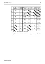
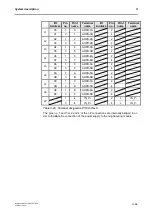
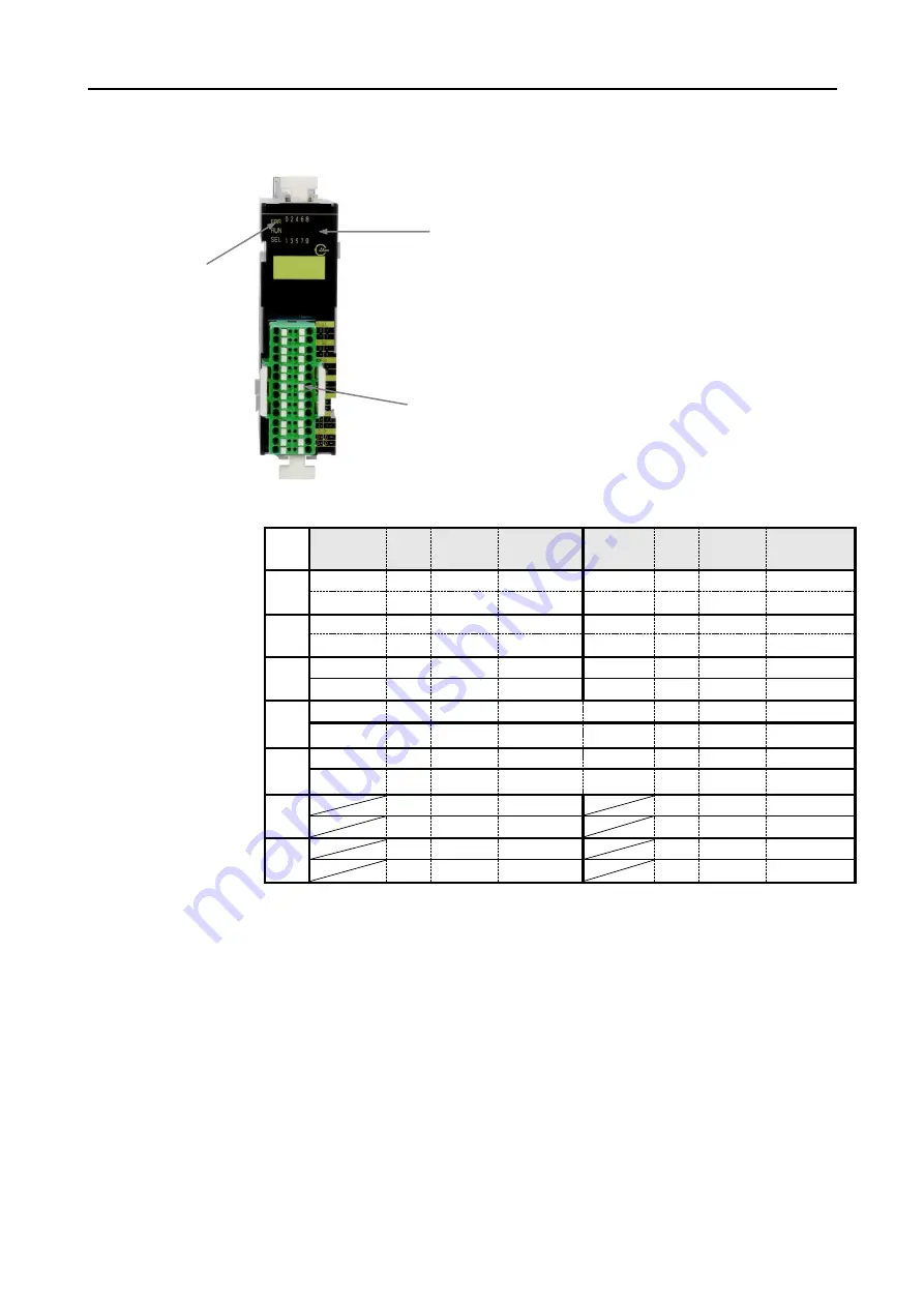
The pins no. 1 and 3 or 2 and 4 of the I-P or O-P connections are internally bridged
in order to facilitate the connection of the power supply to the neighbouring mod-
ules.
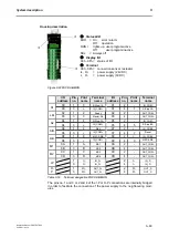
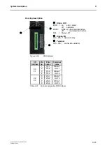
Status LED
ERR = on:
error / alarm
off:
operation
RUN =
lights up: user program active
off:
user program inactive
SEL
= Always off
Display I/O
00 - 09h
= status of I/O
Terminal
00h - 0Fh
= connection sensor / actuator
I+, O+
= power supply ( 24VDC)
I-, O-
= power supply (0VDC)
Summary of Contents for PROTECT-PSC
Page 4: ......
Page 8: ......
Page 112: ......
Page 132: ......
Page 252: ......
Page 265: ...Annex 8 Instruction Manual PROTECT PSC V 2 6R01 04 19 8 5 8 3 EC Type Examination certificate ...
Page 266: ...Annex 8 Instruction Manual PROTECT PSC V 2 6R01 04 19 8 6 8 4 Declarations of conformity W ...
Page 267: ...Annex 8 Instruction Manual PROTECT PSC V 2 6R01 04 19 8 7 8 5 Index ...


