Installation / project planning
Instruction Manual PROTECT-PSC
V 2.6R01 / 04.19
4
–13
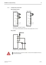
4.3.2
EMERGENCY-OFF (EMERGENCY-STOP) circuitry
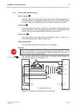
Start/reset level
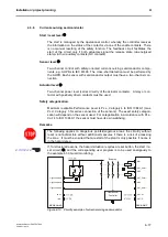
Start button with integrated feedback circuit. The feedback circuit facilitates the
activation of the circuit only if both actuators signal idle status via their auxiliary
contacts (NC contacts). The reset is effected by means of the mechanical latching
function of the EMERGENCY OFF (EMERGENCY STOP) switch.
Sensor level
Two-channel
EMERGENCY
OFF/EMERGENCY
STOP
circuit
to
ISO 13850/IEC 60947-5-5 with cross-short detection. The cross-fault detection
function is only guaranteed if the sensor’s channels switch against different
potential, as shown below.
Actuator level
Two-channel power level (series circuitry of the actuator contacts). A relay or con-
tactor with positively driven contacts must be used.
Safety categorisation
Maximum advisable Performance Level is PL e, Category 4 to ISO 13849-1 (in the
case of series connection of the sensors, observe special features).
Remarks
Start-up occurs only after the release of the start button (monitored start) with the
negative edge.
F
F
i
i
g
g
u
u
r
r
e
e
4
4
-
-
9
9
C
C
i
i
r
r
c
c
u
u
i
i
t
t
r
r
y
y
e
e
x
x
a
a
m
m
p
p
l
l
e
e
o
o
f
f
a
a
n
n
E
E
M
M
E
E
R
R
G
G
E
E
N
N
C
C
Y
Y
-
-
O
O
F
F
F
F
(
(
E
E
M
M
E
E
R
R
G
G
E
E
N
N
C
C
Y
Y
-
-
S
S
T
T
O
O
P
P
)
)
c
c
i
i
r
r
c
c
u
u
i
i
t
t
EMERG
ENCY-
STOP
Enables
START
PSC-S-IN-E
I-P IN-P+
I-P IN-P-
S-Stop-2A
IN_COM-
S-Stop-1B
S-Stop-1A
PSC-S-OUT
OUT-P+
OUT-P-
OUT_COM-
MS3
OUT_COM-
MS2
OUT_COM-
MS1
Summary of Contents for PROTECT-PSC
Page 4: ......
Page 8: ......
Page 112: ......
Page 132: ......
Page 252: ......
Page 265: ...Annex 8 Instruction Manual PROTECT PSC V 2 6R01 04 19 8 5 8 3 EC Type Examination certificate ...
Page 266: ...Annex 8 Instruction Manual PROTECT PSC V 2 6R01 04 19 8 6 8 4 Declarations of conformity W ...
Page 267: ...Annex 8 Instruction Manual PROTECT PSC V 2 6R01 04 19 8 7 8 5 Index ...


