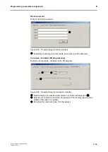
Programming / parameter assignment
Instruction Manual PROTECT-PSC
V 2.6R01 / 04.19
6-55
6.11.3
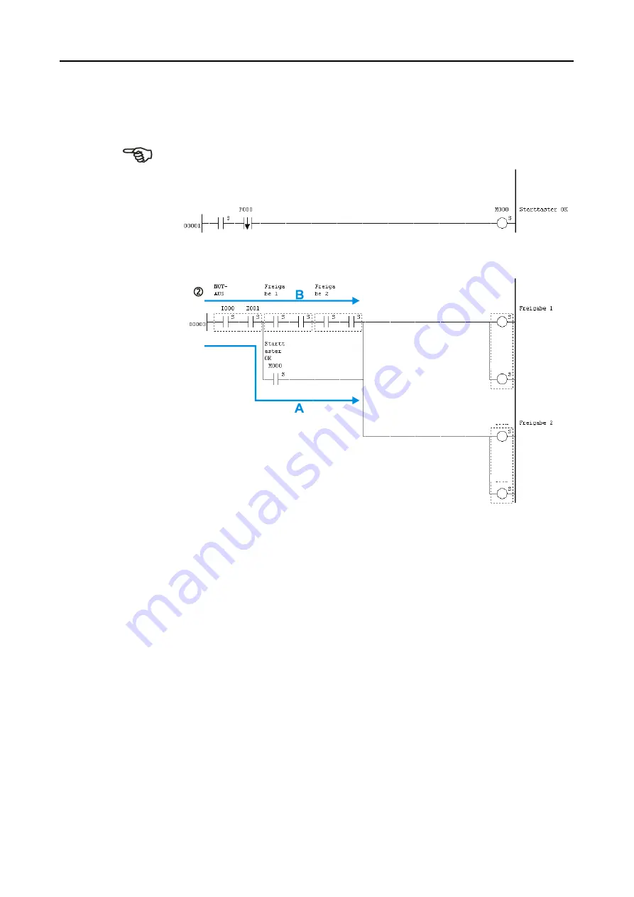
EMERGENCY-OFF (EMERGENCY-STOP) circuitry
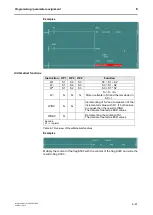
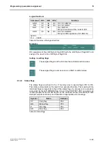
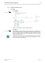
Ladder diagram
Description
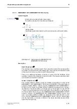
Start / Reset level
The start level has a ‘monitored start’. This means that a start is first produced after
the release of the start button with trailing edge. This prevents unintentional restart
in the event of an error (e.g. short circuit) in the start level.
There is an additional hardware connection in series from the feedback circuit
(auxiliary contact) of the actuators to the start button. This measure prevents start-
up if at least one actuator is operated.
Sensor / actuator level
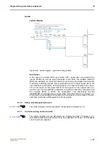
The contacts Q00A to Q00D (= state of enables) are switched in series to the
EMERGENCY-OFF (EMERGENCY STOP) sensor (I000/I001). If the start button is
correctly actuated (M000 = high(1)) and the EMERGENCY-OFF (EMERGENCY-
STOP) circuit is closed, the enables (Q00A to Q00D) are activated via a connect-
ing branch A. The start condition is no longer given in the program run due to P000
= low(0). Connecting branch A is thus interrupted. The connection is now made via
the closed branch B (as long as the EMERGENCY-OFF (EMERGENCY-STOP)
sensor is closed). The EMERGENCY-OFF (EMERGENCY-STOP) ciruit is now
open, and enables (Q00A to Q00D) are deactivated. This state remains in exist-
ence until the EMERGENCY-OFF (EMERGENCY-STOP) circuit is closed again
and the start button is correctly confirmed. The above described process starts
again from the beginning .
I006
Q00C
Q00D
Q00A
Q00B
Q00A
Q00B
Q00C
Q00D
A
A
b
b
b
b
i
i
l
l
d
d
u
u
n
n
g
g
6
6
-
-
4
4
2
2
L
L
a
a
d
d
d
d
e
e
r
r
d
d
i
i
a
a
g
g
r
r
a
a
m
m
f
f
o
o
r
r
E
E
M
M
E
E
R
R
G
G
E
E
N
N
C
C
Y
Y
-
-
O
O
F
F
F
F
(
(
E
E
M
M
E
E
R
R
G
G
E
E
N
N
C
C
Y
Y
-
-
S
S
T
T
O
O
P
P
)
)
c
c
i
i
r
r
c
c
u
u
i
i
t
t
r
r
y
y
It starts with a monitored button (down edge).
The botton is pressed for 2 seconds and released
Safety enable
Feed back signal( back check) must be and connection with a start button
Summary of Contents for PROTECT-PSC
Page 4: ......
Page 8: ......
Page 112: ......
Page 132: ......
Page 252: ......
Page 265: ...Annex 8 Instruction Manual PROTECT PSC V 2 6R01 04 19 8 5 8 3 EC Type Examination certificate ...
Page 266: ...Annex 8 Instruction Manual PROTECT PSC V 2 6R01 04 19 8 6 8 4 Declarations of conformity W ...
Page 267: ...Annex 8 Instruction Manual PROTECT PSC V 2 6R01 04 19 8 7 8 5 Index ...

