Instruction Manual PROTECT-PSC
V 2.6R01 / 04.19
7-2
7.1
Delivery status
The CPU module is delivered in the following state:
•
PIN Code „0000“
•
No PS/PN program
•
No parameters
The user must change the PIN code (“0001” .. “9999”). The new PIN code is
stored in the flash of the CPU module.
7.2
Start-up
Before operating the controller for the first time it is advisable to incorporate a shut-
down device (EMERGENCY-OFF [EMERGENCY-STOP] or similar) into the power
supply.
If you have not already done so, first assemble the back-up battery as described in
Chapter 4.2.4 before commissioning.
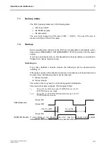
Switching on
If you have installed a booster module, the following must be observed when
switching on.
If the power supplies of the booster and power on module cannot be switched on at
the same time, the following order must be observed:
1.
Booster module
2.
Power module
The reverse order may result in errors during system initialisation.
Take care about power supplies ON timing as follows.
T
on
:
Timing, after turn-ON power supply of POWER Module to turn-ON
BOOSTER Module power supply
T
0FF/ON
: Timing, after turn-OFF BOOSTER Module power supply to turn-ON
POWER Module power supply
If such timing is not observed, an error may be produced during system
initialization and USB communication may become difficult.
POWER Module
Power OFF
Power ON
BOOSTER Module
Power OFF
Power ON
-1ms<T
on
<20s
T
0FF/ON
>5s
Summary of Contents for PROTECT-PSC
Page 4: ......
Page 8: ......
Page 112: ......
Page 132: ......
Page 252: ......
Page 265: ...Annex 8 Instruction Manual PROTECT PSC V 2 6R01 04 19 8 5 8 3 EC Type Examination certificate ...
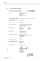
Page 266: ...Annex 8 Instruction Manual PROTECT PSC V 2 6R01 04 19 8 6 8 4 Declarations of conformity W ...
Page 267: ...Annex 8 Instruction Manual PROTECT PSC V 2 6R01 04 19 8 7 8 5 Index ...

