background image

PROTECT 

SRB 200EXi-1R

Mounting and wiring instructions /  
Safety relay module

for emergency stop monitoring and guard door monitoring

3

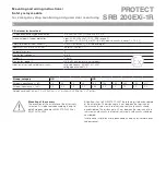
Technical data

Operating voltage

24 VDC –15%/+20%, residual ripple max. 10%

Fuse of the operating voltage

internal fuse F1: T 50 mA/250 V


internal fuse F2: T 100 mA/250 V


Power consumption

max. 3.0 W

Switching capacity of the enabling contacts

230 VAC, 3 A ohmic (inductive with suitable suppressor circuit):

AC-15: 230 VAC/3 A


DC-13: 24 VDC/3 A


Fuse of the enabling contacts

3.15 A slow-blowing

Min. switching capacity

min. 10 V/10 mA

Contact resistance

max. 100 m

 in new state

Utilisation categories

AC-15, DC-13: EN 60 947-5-1:2004

Contact materials/contacts

AgSnO, self-cleaning, positively driven

Switching capacity of the auxiliary contacts
Fuse of the auxiliary contacts
Current and voltage at S11, S12, S21, S22

24 VDC/5 mA

Current limiting at S11, S12, S21, S22

15 mA

Pick-up delay time

approx. 20 ms

Drop-out delay time

at emergency stop: approx. 20 ms


at power failure: approx. 20 ms


Bypass in the case of voltage drops

approx. 15 ms

Air clearance and creepage distance

IEC 60 664-1:2007 (DIN VDE 0110-1), 4 kV/2 (basic isolation)


EN 60 079-11:2007 (VDE 0170/0171 Part 7)


Class of protection

housing: IP 40


terminals: IP 20


installation space: IP 54


Cable connections

Single core: rigid or flexible (with or without wire-end ferrule) 0.25 … 2.5 mm


2

Dual wire with same cross section: 


–  rigid or flexible (with wire-end ferrule without plastics) 0.25 … 2.5 mm

2


–  flexible (with or without TWIN wire-end ferrule) 0.5 … 1.5 mm

2

Tightening torque

0.6 Nm

Max. resistance of entire line

30 Ohm

Cable lengths (at nominal load)

1-channeled without cross-short recognition: 1.5 mm


2

: 1,500 m; 2.5 mm

2

: 2,500 m

2-channeled with/without cross-short recognition: 1.5 mm


2

: 1,500 m; 2.5 mm

2

: 2,500 m

Dimensions (h/w/d)

100 mm/22.5 mm/121 mm

Weight

approx. 230 g

Ambient operating temperature

–25 °C … + 60 °C

Storage temperature

–40 °C … + 85 °C

Mechanical life time

10

7

 switching cycles

Terminal markings

EN 60 947-1:2007

EMC

EN 60 947-5-1:2004

Oscillations

DIN EN 60 068-2-6:1996:

frequency: 10 … 55 Hz


amplitude: 0.35 mm


Environmental conditions

DIN EN 60 068-2-78:2002

CE conformity

acc. directives MRL: 98/37/EC, EMC: 2004/108/EC, ATEX: 94/9/EC

Summary of Contents for PROTECT SRB 200EXi-1R

Page 1: ...ideration with a B10d value view the following requirements refer also to Information within the meaning of DIN EN ISO 13849 1 category 4 PL e acc DIN EN ISO 13849 1 2007 is equivalent to SIL 3 acc DIN EN 61508 2 2002 is equivalent to SILCL3 acc DIN EN 62061 2005 is equivalent to control category 4 acc DIN EN 954 1 1997 For designation of the performance level PL acc DIN EN ISO 13849 1 2007 of the...

Page 2: ...x 20 ms Bypass in the case of voltage drops approx 15 ms Air clearance and creepage distance IEC 60664 1 2007 DIN VDE 0110 1 4 kV 2 basic isolation EN 60079 11 2007 VDE 0170 0171 Part 7 Class of protection housing IP 40 terminals IP 20 installation space IP 54 Cable connections Single core rigid or flexible with or without wire end ferrule 0 25 2 5 mm 2 Dual wire with same cross section rigid or f...

Page 3: ...1 2007 voltage peak value 375 V Group category II C II B External capacitance Co nF 26 36 46 49 160 180 230 280 350 412 External inductance Lo mH 4 0 2 0 1 0 0 5 38 0 5 0 2 0 1 0 0 5 0 2 Reference value of a circuit C 200 nF km L 1 mH km C 200 pF m L 1 µH m Mounting of the sensors The execution of the installation of the intrinsically safe circuits is to be realized according the up to date Europe...

Page 4: ... Connecting and disconnecting of contacts of not intrinsically safe circuits under potentially explosion atmosphere is not allowed The housing may only be cleaned with a wet cloth The life cycle of the module relating to the type of protection nC is at least 15 years After end of this time the module is to be changed or to be send to the manufacturer for a check up Attention The temperature declar...

Page 5: ...49 1 2007 reachable S12 S11 S22 S21 nQS QS E Stop Sensor configuration Dual channel emergency stop circuit with control devices acc DIN EN ISO 13850 2007 EN 418 and EN 60947 5 5 2005 Detects wire breaks and earth leakages in the control circuits Cross shorts between the control circuits are not detected For monitoring the safety circuits the emer gency stop control devices can be executed as simpl...

Page 6: ...ire breaks and earth leakages in the control circuits Cross shorts between the control circuits are detected For monitoring the safety circuits the emer gency stop control devices can be executed as simple apparatus Example devices refer to section Simple apparatus Categorie 4 PLe acc DIN EN ISO 13849 1 2007 reachable Sensor configuration Dual channel control with electro magnetic safety switches ...

Page 7: ...an be used as simple apparatus EX BN 20 3G D K A Schmersal GmbH EX BNS 33 3G D K A Schmersal GmbH EX BNS 120 3G D K A Schmersal GmbH EX BNS 180 3G D K A Schmersal GmbH EX BNS 303 3G D K A Schmersal GmbH without LED version Simple apparatus Installation instructions Application area acc ATEX directive Category 2G 3G Usage in gas explosion endangered areas of the zones 1 and 2 Category 2D 3D Usage i...

Page 8: ...the instal lation The distance of 6 mm between the terminals of the intrinsically safe circuits to other intrinsically safe circuits should be considered The distance of 50 mm between the terminals of the intrinsically safe circuits to other not intrinsically safe circuits should be considered The phasing of the enabling paths 13 14 23 24 may not be different i e only one phase may be connected to...

Page 9: ... Applikationen mit potenzialbehafteten Ausgängen in den Ansteuerkreisen Pos QS unten Querschlusssicher geeignet für zweikanalige Applikationen ohne potenzialbehaftete Aus gänge in den Ansteuerkreisen Achtung Bauelemente nur nach vorgehender Entladung berühren 0V X1 X3 S11 S12 S21 S22 13 14 21 22 PA PA A1 A2 nQS QS UEXi UB Ui K1 K2 SRB 200EXi 1R 0V X1 X2 S11 S12 S21S22 13 14 23 24 PA PA A1 A2 Öffne...

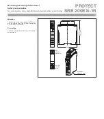
Page 10: ... monitoring 11 Mounting The housing will be attached into the DIN rail with the rear side up slightly tilted forward and pushed above until locked Dismantling Push the rear side of the relay up tilt forward and demount 100 DIN rail acc EN 60715 2001 EXi circuits light blue non EXi circuits grey 22 5 122 121 without BMK ...

Page 11: ...tsschaltsysteme Facsimile 49 0 202 6474 100 Möddinghofe 30 D 42279 Wuppertal E Mail info schmersal com P O Box 240263 D 42232 Wuppertal Internet www schmersal com Production site Elan Schaltelemente GmbH Co KG Phone 49 0 641 9848 0 Im Ostpark 2 D 35435 Wettenberg Facsimile 49 0 641 9848 420 P O Box 1109 D 35429 Wettenberg E Mail info elan schmersal com Internet www elan de 1203578 470 08 02 06 08 ...

Reviews: